第四章 真实世界#
CHAPTER 4 The Real World
真实世界是你我生活的地方。它不在这本书中,也不在某个模拟程序里,甚至不在电路图上的涂鸦中。这些东西都是对真实世界的表征。它们帮助我们理解真实世界是如何运作的。最终,我们所创建和设计的所有电路都会与真实世界发生交互,即使只是一个按钮或一个显示器。因此,我们有必要稍微谈谈一些用于将电路连接到这个庞大而复杂世界的工具。
The real world is the place where you and I live. It isn’t in this book or in a simulation or even the scribbles on a schematic. All those things are representa- tions of the real world. They help us understand how the real world works. At some point, all the circuits we create and design will interface with the real world, even if it is just a button to press or display to look at. It follows that we should talk a bit about some of the things we use to hook our circuits up to the big, bad world.
弥合鸿沟#
BRIDGING THE GAP
如果这本书是在计算机还处于模拟时代写的,那么这一节根本就不需要。然而,现在这些烦人的小数字芯片无处不在,使得这部分内容变得尤为重要。如果你想把你的最新小玩意儿打造成“超炫的数字科技”,你就必须在某个时刻跨越模拟与数字之间的鸿沟。了解一些关于模拟转数字的知识,是个不错的主意。
If this book had been written back when computers were analog, this section wouldn’t even be needed. As it is, the proliferation of those pesky little digital chips gives it top billing. You need to bridge the gap between the analog and the digital at some point if you want to market your latest gadget as“way cool digital technology.” Knowing a bit about how to make the analog-to-digital leap seems like a good idea.
模拟 vs. 数字#
Analog vs. Digital
如果我们把模拟放在拳击台的一角,把数字放在另一角,然后让它们厮杀一番,你觉得谁会赢?在当今世界,数字技术风头正劲,但它到底和模拟技术有何不同?我们来看看。
什么是模拟?它是某个被现代数字工程师遗忘的古老术语吗?并不是。模拟基本上指的是连续变化的信号。这意味着被测量的对象可以在时间上被无限细分。比如,一个信号在1秒内从A变为B。如果你在1秒内观察它,它就会处于A和B之间的某个位置。它是一个连续变量。无论你如何细分时间段,信号中仍然包含信息。
我们感知到的世界本质上是模拟的。颜色从光谱的一端无限渐变到另一端。街上飞驰而过的汽车发出的声音在音量上是连续增强然后减弱的。
开车时,你会根据周围的交通和环境不断调整车速。你周围的世界是模拟的。
那么,数字又是什么呢?“是我的电脑。”你可能会这么说。是的,没错。但让我们从更基础的层面讲讲。举起你手上的一个“digit”(即手指,如果你不知道的话),现在把它放下,再举起来。这就是数字。它要么存在,要么不存在。我不确定“digit”(手指 [1] )是不是“digital”这个词的来源,但它有助于我记住它的含义。因此,数字的最简单形式就是两种状态:要么有,要么没有。
我们再深入一点。如果我们观察手指从完全放下到完全举起的过程呢?仔细看,你会发现数字信号实际上本质上是模拟的。没错。正如我一个工程师朋友常说的那样:“实际上没有真正的数字信号——它们只是长得奇怪的模拟信号。”所以数字只是一个感知方式。你在一个特定的时间窗口内观察某个东西,然后定义它是存在还是不存在。数字是对模拟电平的预设定义。
如果数字其实是伪装成模拟的,那我们干嘛还要用它?早期人们发现数字信号在通信中表现良好。还记得电报吗?它用点/划的数字序列表示字母。为什么它效果好?我们再看一下“数字手指”信号的例子。在远处,观察者很容易判断你的手指是举着还是放下。实际上,这种信号每天都在高速公路上使用!说正经的,重点是:通过使用数字信号进行通信可以避免错误。
那使用数字信号的缺点是什么?电报没持续多久就被模拟通信方式取代了。原因在于带宽,这是衡量信号承载信息量的指标。模拟信号可以承载大量信息。它在给定信号范围内可以具有无限多个电平。
回到手指的例子:如果你有一架好的望远镜,可以从远处聚焦在手指上,就能清楚地看到手指可以表示的不同电平。如果你有一个超大的手指,不用望远镜也可以做到。这说明模拟信号比数字信号更容易表示大量信息。但为此,你需要 更多的能量! [2] (请想象此处有个男人般的咕哝声。)如果你无法从信号中获得更多能量,噪声或其他干扰信息就很容易破坏信号。当你离你最喜欢的广播电台太远时,信号开始变得模糊,这就是这种情况的体现。有时候你可以通过更好的滤波器、放大器等为接收器“提供更多能量”。尽管如此,信号完整性始终是模拟系统面临的挑战之一。
另一方面,要让数字信号传输大量信息,它就必须运行得足够快。过去当人们想听彼此说话时,使用模拟信号更容易。当时的数字技术根本无法足够快地处理音频信息的所有复杂性。因此,多年来,通信主要依赖模拟的信息编码与解码方式。然而,数字在另一个领域悄然崛起——布尔逻辑的应用。 [3]
数字信号可以用来表示布尔语句,一个电平表示真,另一个表示假。计算机就此诞生。诸如“如果这是真的,那就执行那个”的语句可以由机器来执行。布尔逻辑是基于对世界的数字化表示。但别以为只有数字计算机。一段时间内,为了处理大量信息,也曾使用过许多模拟计算机。最终,数字处理速度足够快,取而代之。
If we put analog in one corner of a boxing ring and we put digital in the other corner and then we let them duke it out, who do you think would win? In today’s world, digital is all the rage, but what really sets it apart from analog? Let’s find out.
What is analog? Is it merely some ancient term lost in the world of today’s digital engineers? No, analog basically means a continuously variable signal. It means that the item being measured can be chopped up into infinite little pieces over time. Say, for example, a signal changes from A to B over a 1-second interval. If you look at it before 1 second is over it will be somewhere between A and B. It is a continuous variable. No matter how small you slice up the time segments, there is still a signal with information there.
The world as we perceive it is analog in nature. Colors blend infinitely from one end of the spectrum into the other. The sound as a car races by on the street is heard in a continuously increasing and then decreasing volume level.
As you drive a car, you continuously change speed in response to the traffic and environment around you. The world around you is analog.
So what, then, is digital?“My computer is,” you say. Yes, this is true. But let’s get a little more basic with it. Hold up one of the digits on your hand. (A digit is your finger, in case you were wondering.) Now put it down, now put it up again. This is digital. It is either there, or it is not. I don’t know if digit (as in finger [1]) is where the term digital came from, but it helps me remember what it means. So the simplest form of digital is two states: It’s either there or not.
Let’s go even deeper. What about the time it takes to change state? What if we look at our digital finger as it moves from all the way down to all the way up? If you look at it carefully, you see that a digital signal is really analog in nature. This is true. As one of my engineer friends is fond of saying,“There is no such thing as digital, really—just funny-lookin’ analog.” So digital is really just a mode of perception. You look at something in a specifically determined time frame and define whether it is there or it is not. Digital is a predetermined defi- nition of analog levels.
If digital is really analog in disguise, why even bother with it? Early on it was discovered that digital signals worked well in communication. Remember the telegraph? It used a digital dot/dash series to represent a letter. Why does it work well? Let’s look at our digital finger signal example again. At a distance, it is obvious to the observer whether your finger is up or down. In fact, this sort of signal is used on the freeway every day! All kidding aside, the point is that you can avoid communication errors by using digital signals for communication.
So what is the drawback to using digital signals? The telegraph didn’t last long. It was quickly replaced by analog forms of communication. The reason for this has to do with bandwidth, a measure of the amount of information a signal can carry. The analog signal can carry vast amounts of information. It can, in fact, have an infinite number of levels for a given signal range.
Back to the finger example: If you have a good telescope and can focus in on the finger from far away, you can easily see the varying levels that the finger can represent. The same thing can be accomplished without a telescope if you have a very large finger. This implies that analog signals can represent large amounts of information much more easily than digital signals can. To do this, though, you just need more power! [2] (Imagine a manly grunt here.) If you can’t get more power out of the signal, noise or other unwanted information can easily disrupt the signal. This is what happens when you get too far away from your favorite radio station and it starts to sound fuzzy. Sometimes you can give the receiver“
more power” with better filters, amplifiers, or the like. Nevertheless, signal integrity is one of the struggles with analog systems. On the other hand, to get a digital signal to move a lot of information, it has to work fast. Back when people wanted to hear each other talk, it was much easier to use analog signals. The digital technology of the time simply couldn’t work fast enough to represent all the complexities of the audio information. Thus for many years communication efforts focused on analog encoding and decod- ing of information. However, digital was being used in another domain entirely, in the application of Boolean logic. [3]
Digital signals could be used to represent Boolean statements, one level indi- cating true and the other indicating false. The computer was born. Statements such as,“If this is true, then do that,” could now be executed by machines. Boolean logic is based on a digital representation of the world. Don’t think that there are only digital computers, though. For a while there were many analog computers in use to handle computations involving large amounts of informa- tion. Digital processing speeds eventually increased enough to take over these applications.
我们有了模拟#
So We Have Analog
优点是模拟可以表示大量信息,并且我们周围的世界很容易用模拟信号表示。缺点是无论是发送端还是接收端都需要更多的能量来解析模拟信号,且微弱的模拟信号很容易受到外部干扰。
The upsides are that analog can represent lots of information, and the world around us can easily be represented by analog signals. The downsides are that it takes more power in either the transmitter or receiver to resolve the analog signals, and small analog signals can be easily disrupted by outside influences.
然后是数字#
Then There Is Digital
数字的优点是低功耗传输,以及能够表示逻辑语句。缺点是信息容量有限(带宽低),必须运行得很快才能处理大量信息,且我们周围的世界本质上并非数字。
The pros of digital are low power transmission and the ability to represent logic statements. The cons are information limits (low bandwidth), requiring it to work fast to process large pieces of information, and the fact that the world around us is analog, not digital in nature.
两者兼得的美好愿景#
The Best of Both Worlds
如果我们能两者兼得,不是很好吗?工程师们也是这么想的,于是他们发明了几个缩略词来启动这个过程:ADC(模数转换器)和DAC(数模转换器)。让我们来看看它们是什么。
Wouldn’t it be great to have the best of both worlds? That’s what engineers thought, so they coined a couple of acronyms to get the process started: ADC (the analog-to-digital converter) and DAC (the digital-to-analog converter). Let’s find out what these are.
模数转换与反向操作#
A-TO-D AND BACK AGAIN
什么是模数转换(ADC)?是一种宗教体验吗?是数模转换(DAC)的反义词吗?模数转换就是把真实世界转换成0和1,以便数字技术能够处理它。可以合理地说,数模转换就是这个过程的逆转。在这里我们将探讨模数到数模的转换到底是什么,以及它的用途。
What is A-to-D conversion (or ADC)? Is it a religious experience? Is it the oppo- site of D-to-A conversion (or DAC)? A to D is all about taking the real world and making it into ones and zeros so that digital technology can manipulate it. You can reasonably say that D to A reverses the process. Here we will explore what this A to D to A is and what it is good for.
A 代表模拟#
A Is for Analog
模拟信号通过在预定的时间间隔内将其切分成若干段来转换为数字信号。(这种切分称为采样率。采样率越快,可数字化的频率就越高。)然后在该时间点测量信号,并赋予一个数字值,这个过程称为对信号采样。数字信号(通常用1或0表示)可以组合在一起以表示不同的模拟电平。一个数字可以表示两个电平。如果使用二进制数系统,使用更多的位数可以表示更多的电平。电平的数量是2的位数次幂。四位可以表示16个电平(2^4)。八位可以表示256个电平(2^8),依此类推。一种常见的确定信号电平的方法是使用比较器,如 图 4.1 所示。
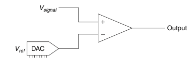
图 4.1 比较器驱动的 ADC。#
研究这个应用。在这个例子中,信号与参考电压进行比较。你从最小值开始逐步增加参考电压到最大值。当信号大于参考电压时,运算放大器比较器将输出高电平,即1。当参考电压更大时,输出为低电平,即0。如果电路知道输出改变状态时的 \(V_{ref}\) 的值,那么此时 \(V_{ref}\) 大约等于 \(V_{signal}\)。我说“大约”是因为总会存在分辨率的问题。如需了解更多内容,请继续阅读。
An analog signal is converted to digital by chopping it up into chunks at prede- termined time intervals. (This chopping is called the sample rate. The faster the sample rate, the higher the frequency that can be digitized.) Then the signal is measured at that point in time and assigned a digital value, which is called sampling the signal. Digital signals (typically represented as 1 or 0) can be crammed together to indicate different levels of analog. A single digit can indicate two levels. If you use a binary numbering system, you get more levels by using more digits. The number of levels goes up by 2 raised to the power of the number of digits. Four digits give you 16 levels (2^4). Eight digits gives you 256 levels (2^8) and so on. One common way of determining the level of a signal is to use a comparator, as shown in Figure 4.1.
FIGURE 4.1 Comparator-driven ADC.#
Study this application. In this case, the signal is compared to a reference voltage. You increase the reference voltage from min to max. When the signal is larger than the reference voltage, the op-amp comparator will output a high, or a 1. When the reference voltage is the larger of the two, the output will be low, or a 0. If the circuit knows the value of \(V_{ref}\) at the time the output changes state, this is when \(V_{ref}\) is approximately equal to \(V_{signal}\). I say approximately because there is always a question of resolution. For more on this topic, read on.
D 代表数字#
D Is for Digital
现在我们有了数字信号,我们可以用它做很多有趣的事情。我们可以传输它、接收它、操作它,而不用太担心信号的丢失。但接下来是什么?比如我们将吉他音乐转换为数字格式,以加入一些酷炫的音效。你不能仅仅把这些数字数据直接输出让人听见。它必须被转换回模拟信号。为什么?因为我们对某些事物在模拟格式下的感知更敏锐。如果你不相信我,看看你车上的速度表;我敢打赌它是个模拟表盘。(有些东西我们喜欢用数字方式看,但那通常是为了避免处理无限的增量;看看你车上的里程表就是个例子。[4])
为了将数字信号转换回模拟信号,电路必须模拟它所代表的模拟信号。这总是需要某种滤波过程。有很多方法可以实现数模转换。我最喜欢的方法之一是脉宽调制(PWM)。在PWM电路中,设备的输出以一定频率开关——参见 图 4.2。其开启与关闭所占的时间百分比,就是它所代表的模拟信号大小。这个百分比称为占空比。
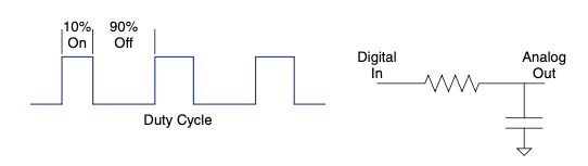
图 4.2 通过占空比控制的模拟输出。#
数字PWM信号输入到一个低通滤波器中,该滤波器会去除信号的开关频率,最终留下一个模拟信号。这个信号可以表示的电平数量取决于PWM信号的分辨率。即PWM在不同占空比下开关的能力。例如,一个能以5%占空比增量切换的PWM,其分辨率就比一个能以1%增量切换的电路低——参见 图 4.2。这意味着数字信号只能表示模拟信号的离散电平。这些电平构成了信号的分辨率。
为什么分辨率如此重要?我们在比较器示例中提到,电路知道 \(V_{ref}\) 是什么电平。它是怎么知道的?它必须以某种方式生成该值。这是通过某种数模转换(DAC)过程实现的。而DAC过程的分辨率将决定ADC过程的分辨率。
所以我们就这样,从模拟到数字,再回到模拟。这真的是一个循环。让我们来看一些例子,看看这个概念是如何运作的。
Now that we have a digital signal we can do lots of fun things with it. We can trans- mit it, receive it, and manipulate it without worrying much about signal loss. But what is next? Say we convert guitar music into digital format to add some neat sound effects. You can’t simply send the digital data back out to be heard. It must be converted back to analog. Why? Because there are certain things we perceive well in an analog format. If you don’t believe me, take a look at the speedometer in your car; I’ll bet it is an analog gauge. (There are some things we like to see digitally, but usually that’s so we don’t have to deal with infinite increments; look at the odometer in your car for this example. [4])
To convert a digital signal back to analog, the circuit has to simulate the ana- log signal it represents. This always requires some kind of filtering. There are many ways to convert digital to analog. One of my favorites is by pulse width modulation (PWM). In a PWM circuit, the device’s output switches on and off at a given frequency—see Figure 4.2. The percentage of time it is on versus off is the amount of analog signal it represents. This percentage is called the duty cycle.
FIGURE 4.2 Duty cycle-controlled analog output.#
The digital PWM is fed into a low-pass filter that removes the switching fre- quency of the signal, essentially leaving an analog signal. The number of levels that this signal can represent depends on the resolution of the PWM signal. This is the capability of the PWM to be switched on and off at varying duty cycles. For example, a PWM that could switch on and off in increments of 5% duty cycle would have less resolution than a circuit that can handle increments of 1% duty cycle—see Figure 4.2. This means that digital signals can repre- sent only discrete levels of analog signal. These levels are the resolution of the signal.
Why is resolution so important? We stated earlier in the comparator example that the circuit knows what level Vref is at. How does it know that? It must generate it somehow. It does so with some type of DAC process. It is the resolution of that DAC process that will determine the resolution of the ADC process.
So there we are. We went from analog to digital and right back to analog again. It really is a circle. Let’s look at some examples to see this concept in action.
要进行一点数模转换,才能完成一次模数转换#
IT TAKES A LITTLE D TO A TO GET A LITTLE A TO D
不久前,我在向一位工程师朋友解释我关于“世界本质上是模拟的”的观点。他发来如下回应邮件:
我想对你关于“我们感知的世界是模拟的”这一说法提出反驳。我认为,自然界中的数字感知和模拟感知一样多,甚至更多。比如:生或死、黑夜或白昼、开或关、湿或干、植物或动物、主导或服从、捕食者或猎物、饥或饱、粗糙或光滑、冷或热、模糊或清晰、单一或多样、伪装或警告、平原或山地、森林或沙漠、风暴或晴朗、噪音或寂静、失明或视力、男性或女性、丰年或饥荒、生存或死亡、开启或关闭,等等。当然,像温暖、微风、日落和杂食这类感知也存在,但总体来说,我认为我们的自然感知更偏向数字。[5]
从很多方面来说,他在这段优雅评论中说得是对的;但他所说的是我们的感知。我们把来自世界的模拟信息划分到“数字桶”中。(当然,比如冷热之间确实存在中间状态。)我认为我们之所以这么做,是为了便于决策、减少信息存储量,并简化交流。我们在合适的时候施加数字化的感知。也许我更好的说法是:“世界本质上是模拟的,而我们赋予其数字化的感知。”有了这个前提,让我们继续深入模数转换的一些基础机制。我们从前几页讲到的 DAC 和简单比较器开始。
一个简单的比较器会根据一个输入是否高于或低于另一个输入输出高电平或低电平(参见 图 4.3)。这是使用比较器的绝佳时机,因为数字电路喜欢明确的高低电平信号。我们来看看这个电路的基本过程:你将一个数字值转换为一个已知的模拟电平,与一个模拟信号进行比较,如果它们非常接近(这时分辨率就很关键),那么你输出的数字值就代表了该模拟信号的数值。
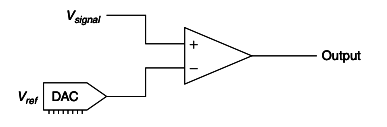
图 4.3 比较器驱动的 ADC。#
我们来看一个例子。你正在转换一个实际值为 4.45 的模拟信号。你试着用 DAC 输出 1,比较器说“更高”(它通过输出 1 或高电平来表示 [6] )。你接着输出 2,比较器还是说“更高”。然后你输出 3,再输出 4。猜猜每次比较器怎么说?没错,它每次都说“更高”。那接下来你试什么?当然是输出 5。这时比较器说“更低”。现在你的电路知道信号值在 4 和 5 之间。此时你从这两个值中选一个 [7] (假设 DAC 在 0–5 的范围内只输出六个离散电平)。DAC 的步进越小,就能越精确地估算模拟信号的值。步进越小,信号的分辨率就越高。
还有一种比简单遍历所有可能值更好也更快的方法。(现在我们增加 DAC 的分辨率来说明这个问题。)首先将 DAC 的第一次输出设为整个范围的一半。这种情况下你输出 2.5。观察比较器的输出并进行逻辑决策(数字信号在这方面表现很好)。你可以看出比较器是否输出“更高”,从而排除掉 2.5 以下的所有值。接着你输出剩余范围的一半——也就是 3.75。再次观察比较器输出并排除更多不可能值(高电平表示排除其以下所有值,低电平则排除其以上所有值),然后再输出剩余范围的一半。重复这个过程,直到达到分辨率极限为止,你就能得出该模拟信号的近似值。这种快速模数转换方法叫做逐次逼近,常用于需要高速 A/D 转换的场景。
你是否注意到,在讲解模数转换过程时我经常使用“近似”这个词?这是因为数字信号永远无法真正等同于模拟信号;它总得在某处“画一条线”。别忘了数字意味着存在离散步进。模拟,按照定义,是具有无限增量的。既然你已掌握 A/D 转换的基本原理,我们再来看几个 DAC 电路的例子,以便更直观地理解。[8]
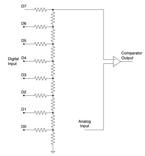
图 4.4 R2R 电阻梯。#
这是实现数字电压输出的一种巧妙方法,你可以将 R2R 电阻梯封装在一个紧凑模块中,如 图 4.4 所示。注意不要在没有缓冲的情况下将其接到低阻抗设备上,否则其输出电平会受到外部负载的影响。
这个电阻梯是如何工作的?一个数字字节被输出到电阻梯上,电阻梯将电压电平转换为比较器的输入电压。需要注意的是,最高有效位(MSB)对输出影响最大,最低有效位(LSB)影响最小。这种方式非常适合前文所述的逼近法。你只需将想要的 DAC 值加载到电阻上,然后观察输出信号即可。这种方式非常快。最大的问题是它需要很多输出引脚。(这些引脚必须能够吸收或提供足够电流才能正常工作。)有一点要注意:确保你的处理器能承受电阻梯的负载。我多年前在某个电路应用中使用的 Zilog 处理器表现良好,甚至还有板载比较器用于 ADC 过程,但我用了所有的引脚,几乎没有剩余信号引脚可用。
在这个电路中,PWM 信号的占空比从 0% 开始逐渐升高,直到超过模拟信号值,比较器就会指示变化——参见 图 4.5。模拟电压由 PWM 信号发生状态变化时的占空比来表示。RC 滤波器必须将 PWM 信号转换为基本的模拟电平。这意味着 PWM 的开关速度必须远远快于你所要数字化的信号的变化速度。
这种方法依赖于基本 RC 电路的瞬态响应(参见 图 4.6)。阶跃输入使比较器的输入根据 RC 电路的响应时间增加。RC 电路的输出等于
\(Vi(1 - e^{-(t/\tau)})\)。因此,如果你知道时间常数 tau(即 R * C),就可以根据时间计算电压。在某些微控制器中,这种计算可能比较繁琐,但很多时候并不需要很高精度,可以使用一个查找表来实现。在许多情况下,还会为该电路增加一个低电阻放电路径,以确保 RC 电路的输出从零开始。
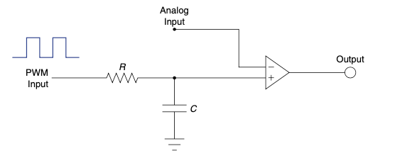
图 4.5 PWM 斜坡。#
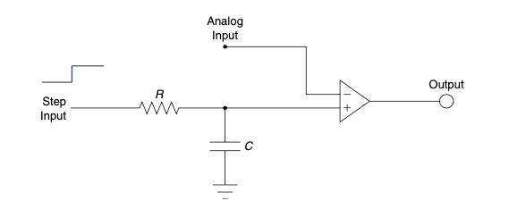
图 4.6 RC 充电时间。#
这个电路的缺点是需要进行曲线计算,但信号的前三个时间常数是相当线性的近似。根据具体应用,这可能就足够了。(回顾第一章开头关于电子学与手榴弹的类比,看看什么时候“够用就行”。)如果你的任务要求不高,也不接近电压上限轨,就可以简单地计时而跳过那些复杂的计算,从而使这成为一种快速、廉价、实用的 ADC。
以上就是三种获取模拟信号数字近似值的简便方法。这些电路都可以单独作为 DAC 使用。
最后一点:如今微控制器越来越普遍地内置了 A/D 转换器。然而,它们几乎都基于使用 DAC 实现 ADC 的原理。学习本节内容可以帮助你了解这些器件内部究竟是怎么工作的。你对内部原理了解得越多,你就会成为更出色的工程师!
A while ago I was explaining my thoughts on the world being analog in nature to a fellow engineer. He emailed me the following response:
I would like to provide counterpoint to your assertion that“the world as we perceive it is analog in nature.” I think that there are as many, if not more, natural digital perceptions as there are analog. Some samples: alive or dead, night or day, open or closed, wet or dry, flora or fauna, dominant or submissive, predator or prey, hungry or full, coarse or smooth, hot or cold, fuzzy or sharp, open or closed, single or multi, camouflage or warning, flat or mountainous, forest or desert, stormy or clear, noise or silence, blind or seeing, male or female, feast or famine, survive or die, on or off and so on. Granted, things like warm, breezy, sunsets, and omnivorous are there, but for the most part, I think our nature perceptions are digital. [5]
In many ways he is correct in his eloquent comments; however, he refers to our perception. We place the analog information from the world into“digital buckets.” (There are certainly levels between hot and cold, for example.) I think the reason we do this is to facilitate decision making, to limit the store of infor- mation, and to ease communication. We impose a digital perception when it makes sense to do so. A better phrase I could have used is something like, “The world is analog in nature, upon which we impose our digital perceptions.” With that in mind, let’s look at some more of the nuts and bolts of A-to-D conver- sion. We’ll start with the DAC and a simple comparator from a couple of pages back.
A simple comparator will output a high or low signal depending on whether one input was above or below the other (Figure 4.3). This is a great time to use a comparator, since digital circuits like obvious signals such as high and low. Let’s drill the basic process of this circuit: You convert a digital number to a known analog level, compare that to an analog signal, and if it is close to the same value (here is where resolution counts), the digital number you output represents the analog value.
FIGURE 4.3 Comparator-driven ADC.#
Let’s do an example. You are converting an analog signal with the actual value of 4.45. You try outputting a 1 on your DAC. The comparator says“higher” (it does this by outputting a 1, or a high signal [6] ). You then try outputting a 2. The comparator says“higher.” Now you try a 3, then a 4. Guess what the com- parator says each time. That’s right, it says“higher.” So what do you try next? Of course, you try a 5. Then the comparator says“lower.” Now your circuit knows that the value is between 4 and 5. At this point you pick one of these two values [7] (assuming in this case that the DAC only outputs six discrete levels over a range from 0–5). The smaller the steps or increments that you can output with the DAC, the closer you can estimate the value of the analog signal. When you make the steps in the DAC smaller you increase the resolution of the signal.
There is a better and faster way than merely sweeping across all the values in the range. (We will increase the resolution of our DAC now to illustrate this point.) Start by making your first output on the DAC equal to ½ of the entire range. In this case you output 2.5 on the DAC. Now look at what the comparator says and make a logic decision (digital is good for this sort of thing). You can see whether the comparator says“higher,” and you can eliminate everything below 2.5. So you make your next output equal to half of the remaining range—in this case, you output 3.75. Look at the comparator again and eliminate some more possibilities (a high eliminates everything below the number, whereas a low eliminates everything above the number), then output half the remaining range. Repeat this process until you are out of resolution and you will have an approximation of the analog signal. This is a very fast way of converting an analog signal known as successive approximation. It is often used when high- speed analog-to-digital conversion is needed.
Did you notice that I often use the word approximation as the A-to-D process takes place? This is because a digital signal can never truly equal an analog signal; it must always draw the line somewhere. Do not forget that digital means that there are discrete steps involved. Analog has, by definition, infinite increments. Now that you have the basic idea behind the A-to-D conversion process, let’s look at some examples of DAC circuits to develop a more intuitive understanding. [8]
FIGURE 4.4 The R2R ladder.#
This is a slick way to get a digital voltage level, and you can get the R2R ladder in a nice compact package, as shown in Figure 4.4. You must take care not to hook it up to any low-impedance devices without buffering, since its output level can be easily affected by external loads.
How does the ladder work? A digital byte is output to the ladder, which changes the voltage level to the input of the comparator. You should note that the MSB (most significant bit) has the most effect on the output. The LSB (least significant bit) affects the output the least. This works very well with the approximation method described earlier. You simply load the DAC value you want on the resistors and look at the output signal. It is very fast. The biggest downside is that it uses a lot of output pins. (The output pins must be able to sink or source sufficient current to work correctly.) One caution: Make sure your processor can handle the output load of the ladder. The Zilog processor I used in one application of this circuit years ago worked fine and even had an onboard comparator for the ADC process, but I did use every pin, leaving little room for additional signals if needed.
In this circuit, the duty cycle of the PWM signal is ramped up from 0% until it passes the value of the analog signal, as indicated by the comparator—see Figure 4.5. The analog voltage is represented by the percentage of the PWM signal when the comparator changes state. The RC filter must turn the PWM into basically an analog level. This means that the PWM must switch significantly faster than the speed of the signal you are trying to digitize.
This method relies on the transient response of the basic RC circuit (Figure 4.6).
The step input causes the input to the comparator to increase according to the
response time of the RC circuit. The output of the RC circuit is equal to
\(Vi(1 - e^{-(t/\tau)})\). So if you know the value of tau, which is R * C, you can calculate
the voltage based on the time it takes to pass the input. This can be tedious to
calculate in some micros, but often high accuracy is not needed and a lookup
table of the values can be implemented. In many cases, a lower-resistance discharge path is added to this circuit to ensure that the output of the RC circuit begins at zero.
FIGURE 4.5 PWM ramp.#
FIGURE 4.6 RC charge time.#
The downsides to this circuit are the curve calculations, but the first three tau of the signal are a fairly linear approximation. Depending on the application, that might be good enough. (Review the connection between electronics and hand grenades way back at the beginning of Chapter 1 to see when things are“good enough.”) If your task isn’t too demanding and you don’t get too close to the upper rail, you can simply count time and toss out that complex calculation, making this a quick, cheap, and dirty ADC.
So there you have three easy ways to get a digital approximation of an analog signal. All these circuits are perfectly fine to use as DACs only. One last thought: These days a built-in A/D converter is an increasingly com- mon feature on a microcontroller. However, they nearly all work on the princi- ple of using a DAC to make an ADC. Studying this section can help you to get an idea of what is really going on in there. The more you know about how it works on the inside, the better engineer you will be!
数字信号处理#
Digital Signal Processing
DSP,即 数字信号处理,指的是对从模拟信号数字化后的数据进行操作。在很多情况下,如音频和视频,信号在经过 DSP 处理后还会被转换回模拟信号。关于 DSP 的书籍有很多,比本书对该主题的覆盖更为深入。然而,在这里我只希望对这个话题提供一点基本理解。
DSP 的优势之一是可以即时更改滤波器的参数。这使得工程师能够创造出各种新颖的信号处理解决方案,这些在传统的模拟设计中很难实现。通常,DSP 解决方案的成本也高于模拟方案,因此要确保你确实需要它。不要在本来用一个 25 美分的运算放大器就能完成任务的地方,硬是塞一个 5 美元的 DSP 芯片进去。这并不是说 DSP 没有用武之地。没有 DSP,我们就不会有 MP3、WMA、AC3、AAC、MP4、WiFi,以及一大堆可以炫耀的缩写!说起来,DSP 技术可能比其他任何技术都“制造”出更多缩写词!
DSP, or digital signal processing, refers to manipulating data that is digitized from an analog signal. In many cases, such as audio and video, the signal is converted back to analog after DSP occurs. Many books on DSP are available that offer far better coverage of this subject than this one. However, here I only hope to create a bit of understanding on this topic.
One of the advantages of a DSP is the ability to change parameters of the filters on the fly. This allows engineers to create all sorts of new solutions to processing signals that are very difficult to achieve with comparable analog designs. Typically, a DSP solution is also more expensive than an analog one, so be sure you really need it. Don’t slap a five-dollar DSP chip in the circuit when a 25-cent op-amp will do the job. That is not to say DSP doesn’t have its place. Without DSP, we wouldn’t have MP3, WMA, AC3, AAC, MP4, WiFi, and a whole other slew of acronyms to spout about! Come to think of it, DSP technology might be responsible for more acronyms than any other!
拇指法则(Thumb Rules)
模拟信号是连续可变的信号。
数字信号是对特定模拟电平的预定义。
数字信号具有离散的步进。
分辨率是离散步进之间的间距。
DAC 经常被用于 ADC。
Analog is a continuously variable signal.
Digital is a predetermined definition of a specific analog level.
Digital signals have discrete steps.
Resolution is the distance between the discrete steps.
DAC is often used for ADC.
当器件不够理想时#
WHEN PARTS AREN’T PERFECT
在我们讨论器件可能出现的问题之前,需要引入等效电路的概念。它其实很简单:要构建一个等效电路,就是用理想器件的组合来表示一个元件的所有特性和缺陷。
这么做有两个好处:首先,最显而易见的好处是可以对器件的非理想效应进行建模;其次,对 Darren 世界来说更重要的是,通过看到一个真实元件由哪些理想器件组合而成,你可以更容易地将对理想器件的基本理解应用于对真实器件行为的把握。
Before we get into the problems that parts can have, we need to introduce the concept of an equivalent circuit. It is pretty simple: To create an equivalent circuit, you represent all its idiosyncrasies with combinations of perfect components.
This is good for two reasons: First and most obvious, it makes it possible to model the effects of the imperfections. Second, and most important in the World of Darren, is that seeing the combinations of the parts that make up a real com- ponent makes it easier for you to apply the basic understanding of the perfect parts to grasp what the real part is doing.
一切皆无处不在#
Everything Is Everywhere
三种基本电学元件就像海滩上的沙子,它们无处不在。某种程度上,它们甚至比你凉鞋里的沙子还“猖獗”,因为一个元件的效应可能在另一个元件中也能被发现。正是这个事实,造成了电路的实际行为与计算公式预测行为之间最常见的误差之一。这也是为什么数据手册如此重要——即便是描述最基本元件的手册也不例外。数据手册会对元件进行特性说明,描述这些误差来源。
大多数教科书将这些效应称为 误差源,因为它们造成了理想器件与实际器件之间的差异。每个元件中还有其他类型的误差源,后面我们还会讨论其中一些。但那些烦人的 R、L 和 C 的某种组合几乎存在于任何地方。(我希望现在你已经越来越清楚为什么我们一开始要反复强调这三个基本元件。现在正是你恍然大悟的时刻,对自己说:“我终于明白为什么要把这些基本元件烂熟于心了!”)
当你在查找误差源时,最通用的指导原则是问自己:“这个误差源足以解释我所观察到的效应吗?”我们以二极管为例。一个反向偏置的二极管会表现出一点电容,通常在皮法级别。
考虑如 图 4.7 所示的电路。如果你将示波器探头连接到输出端,并翻转开关,你会看到如 图 4.8 所示的波形。由于该二极管存在电容,在这种情况下你会预期看到一个 RC 曲线。但这真的是该二极管的误差源导致的吗?还是另有原因?
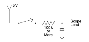
图 4.7 用于检查的电路。#
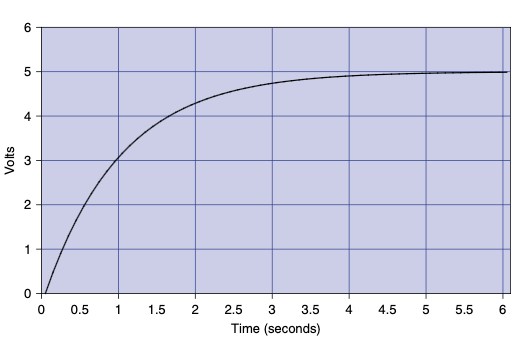
图 4.8 你在示波器上看到的 RC 曲线。#
这时就该查阅数据手册了;你查看所用二极管的规格,发现其典型电容是 100 皮法。将这个值代入 RC 电路的响应时间公式:
你得到的时间常数是 10 微秒。再看看示波器,这次你注意到这条曲线达到约 63% 的时间,记住那大概是一倍时间常数(tau)时的幅度。作为一名敏锐的示波器使用者,你使用光标工具测量出信号达到最终值一半所需的时间约为 1 秒。你应该对自己说:“这不对劲。如果是二极管引起的,它的响应应该快得多。”
这个故事的寓意是:要预期每个元件都带有一定量的三种基本元件特性,但也要了解它们的量级,这样你才能判断它是否造成了你所观察到的效应。
The basic three electrical components are like sand at the beach. They get into everything. In a way they are more prolific than sand in your sandals since the effect of one basic component can be found in another. This fact is one of the most common causes of error you will have between the way the equa- tion predicts a circuit will work and the way it actually operates. Chalk this up as one of the reasons datasheets are so important, even the ones that describe the most basic components. Datasheets will characterize the components, describing these error sources.
Most texts call these effects error sources since they are what makes the difference between a perfect or ideal component and what you actually have to work with. There are other types of error sources in every component, and we will discuss a few of them later on, but those pesky R, L, and C in some combination or another are pretty much everywhere. (I hope the reason for drilling the basics of these components is becoming more and more clear. It is appropriate to experience an“a-ha!” moment right now and say to yourself,“Now I see why I need to know those basic parts by heart!”)
The most general guideline to follow when you are looking for error sources is to ask yourself the following: Is this error source enough to account for the effect I am seeing?” Let’s consider a diode as an example for a moment. A diode has a bit of capacitance when it is reverse-biased, typically in the picofarad range.
Consider the circuit shown in Figure 4.7. If you hook your scope lead to the output, and flip the switch, you see what’s shown in Figure 4.8. Since there is capacitance in this diode, an RC curve is what you would expect to see in a situation like this, but is it really due to the error source in this diode or is it caused by something else?
FIGURE 4.7 Circuit to examine.#
FIGURE 4.8 RC curve seen on your scope.#
Here is where the datasheet comes in; looking at the specs on the diode you are using, you find out that this capacitance is typically 100 pf. Plug that into the equation for the response time of an RC circuit:
The number that pops out is 10 μS. Taking a look at the scope again, you now pay attention to the time it takes for this curve to get to about 63%, remembering that is about how far this curve gets in one time constant, or tau. Being such an astute scope operator, you use the cursors on your tool and you measure a time of about 1 second for the signal to get a little over halfway to its final value.“That doesn’t make sense,” you should be saying to yourself,“If the diode is responsible, it would have to be much faster.”
The moral of the story is to expect every component to have some amount of the basic three, but understand the magnitude so you can decide if it is causing the effect you are seeing.
误差源:理想 vs. 现实#
Error Sources, Ideal vs. Real
在你设计的任何电路中,都会存在误差源——例如不够完美的地方、稍有偏差的传感器、不完全符合规范的元件,或是各种各样的问题。
你该怎么处理它们?如果这些误差源不会引发任何问题,那就什么也不用做。例如,如果你有足够的电源,一个漏电容可能根本无关紧要。然而,如果电路是由电池供电的,你可能就会面临麻烦。首先也是最重要的,是要确定该误差源是否真的是个问题,然后再考虑如何解决它。
一旦你认定某个特定的误差源确实是问题,可以通过以下三种方式应对:
换一个更好的元件。堵住一个漏电容的“漏洞”是很难的;[9] 它可不像那个把手指堵在堤坝上的男孩——你没法把手指插进去就把问题解决了。有时候你唯一的选择就是换个元件。例如你可以选用钽电容代替电解电容。但要注意,更好的元件通常也更贵,所以要明智地花钱,而不是随意乱花。不过也要指出,这是解决问题最快的方法,因为不用更改电路设计。
用另一个元件强化薄弱环节。比如,电解电容的频率响应问题可以通过并联一个较小的电容来解决,这个小电容在高频下没有问题。(你可能已经注意到,稳压器的参考设计就是这么做的,以保证输出稳定。现在你知道为什么了。)
通过设计排除误差。这种方式需要最多的工程努力,因为目标是改变电路设计,使误差变得不再重要。众所周知的运算放大器就是这类努力的一个例子。[10] 既然我们已经了解如何应对误差问题,接下来来看看一些常见元件和典型的误差来源。这部分内容是基于个人经验的概述,不能替代用数据手册来治失眠的那种详细程度。
In any circuit you design, there will be sources of error—things that simply aren’t perfect, sensors that are off a little, parts that aren’t quite to spec, or any myriad of problems.
What do you do about it? Nothing, if the error source isn’t causing you any problems. For example, a leaky cap might not really matter if you have plenty of power available. However, if the circuit is running on batteries you could have a problem on your hands. First and most important, determine whether the source of error is an issue or not before you go about trying to solve it.
Once you figure you have a problem on your hands with a particular source of error, there are three ways to deal with it:
Get a better component. It’s tough to plug the hole in a leaky cap; [9] it isn’t like the boy at the dike—you can’t put your finger in the hole and stop the leak. Sometimes your only choice is another component. In this case you might specify a tantalum cap instead of an electrolytic. Consider, however, that often the better component costs more, so spend wisely, not indiscriminately. Do note, however, that this is usually the quickest way to solve the problem since the design doesn’t have to change.
Shore up the weak component with another component. For example, the frequency response problems with electrolytic caps can be dealt with by adding another cap in parallel, a smaller one that has no problems with higher frequencies. (You might have noticed regulator reference designs do just that to assure a stable output. Now you know why.)
Design the error out. This approach will take the most engineering effort, since the goal is to change the design so that the error is no longer significant. The proverbial op-amp is an example of this type of effort. [10] Now that we know how to deal with the problem, let’s look at some common parts and typical sources of error. This will be an overview based on personal experience. It is no substitute for curing insomnia with a good datasheet.
电阻器#
Resistors
我得说,在三种基本元件中,电阻器是最稳定、最可预测的。碳膜电阻器的电感和电容都非常小。除非你是在处理射频或高速时钟,否则几乎不会出现相关问题。在大多数情况下,PCB 设计造成的影响都要大于电阻本身。
这些常见电阻器的最大问题可能是发热。如果超过或接近额定功率,它们的阻值就会明显偏离标称值,因此最好在功率设计上给自己多留一些余量。
另一种常见的电阻器,通常用于高功率应用,是线绕电阻器,其内部是一圈绕线,外部是陶瓷封装。在这种情况下,由于线圈的存在,电感效应可能会很显著。而我们知道,线圈就会产生电感。为了解决这个问题,现在有一个完整的低电感功率电阻器产业可供选择。
I would have to say that resistors are the most stable and predictable of the three basic components. Carbon film resistors have very little inductance or capacitance. It is rare that you will have a problem with this unless you are dealing with radio frequencies and high clock speeds. In most cases the effect of the PCB design will be worse than the resistor itself.
The biggest issue with these common resistors will likely be heat. Exceeding or coming close to the wattage rating of these parts will make them vary significantly from their nominal value, so it is a good idea to give yourself plenty of headroom with these resistors.
Another common resistor typically used in higher-power applications is a wirewound coil with a ceramic block molded around it. In this case inductance can be a significant effect since there is a coil of wire and, as we know, coils of wire make inductors. There is a whole industry of low-inductance power resistors that you can get to work around this problem.
电容器#
Capacitors
根据我的个人经验,我从未见过一个接近完美的电容器。一个完美的电容器不会发热,但现实中它们确实会发热。你自然可以得出结论:电容器具有某种电阻成分。事实上,它们确实有,这种成分被称为 ESR,即等效串联电阻。
根据公式,一个 10μF 的电容器在 100kHz 时应该具有与 0.1μF 电容差不多的阻抗,但现实却并非如此。这就是为什么你经常会看到电源电路上一个大电容旁边配着一个小电容。几乎所有的电容在不同频率范围下电容值都会变化。
大电解电容经常会像筛子一样“漏电”。对此没有特别容易的处理方式。你要么忍受它,要么换个更好的元件。相信我,如果你正试图做一个超低功耗的电路,最糟糕的事情就是电容四处乱“漏”电子。
还有一件我吃过苦头的事是:电容器的标称电容值只有在额定电压下才有效。有时候,电压额定值选得太高,实际电容值可能和你预期的不一样。如果你不按极性标注给极性电容加偏置,它们就会表现得像一个二极管。许多电容器的电容值在温度变化范围内会变化 20%;你可能不希望它们被放在 PCB 上靠近功率电阻的位置。
电容器的寓意:为特定应用选择电容器时,你需要仔细阅读其数据手册。
In my personal experience, I have never seen a cap that even comes close to being perfect. A perfect cap would not heat up, but in fact they do. The natural conclusion you should come to is that capacitors have some type of resistive component. In fact they do, and it is called ESR, or equivalent series resistance.
According to the equations, a 10-μf cap should have nearly the same impedance at 100 K Hz as a 0.1 μf cap does, but alas this is not the case. That is why you often see a large cap with a small cap next to it on a power-supply circuit. Nearly all caps vary in capacitance over a frequency range.
Big electrolytic caps often“leak” like a sieve. There is no particularly easy way to deal with that. You have to live with it or get a better part. Believe me, if you are trying to make a really low-power circuit, the last thing you want is a cap spilling electrons all over the place.
One other thing I had to learn the hard way is that a cap only meets the rated capacitance when at the rated voltage. Sometimes overrating the voltage on the cap too much can leave you with a different capacitance than you expect. Polarized capacitors will act like a diode if you don’t bias them according to their markings. Many caps will vary 20% over their temperature range; you might not want them next to a power resistor on your PCB.
The moral of the cap story: You need to peruse capacitor datasheets carefully when you are picking them for a particular application.
电感器#
Inductors
因为电感器通常是绕线制成的,所以你可以想象电阻是它们最常见的误差来源之一,你猜对了。电阻确实是电感器的主要误差源。这通常会导致发热和功耗问题,或许你并不希望出现这些问题。在设计阶段尽量减小电感器中的电流,就可以减小电阻的影响。
很多电感器是绕在某种铁芯材料上的。当磁场超过铁芯能承受的限度时,就会发生所谓的磁芯饱和现象。
导线之间存在一些电容效应,但非常微小,本书中将忽略它们。如果你正在处理千兆赫频率,那你可能正在读一本比我聪明得多的人写的专门书籍。
Since these are most often coils of wire, you might imagine that resistance is one of the most common sources of error in an inductor, and you’d be right. Resistance is a major source of error in inductors. This usually causes heat and power usage that you may or may not want. Minimizing the current flow through the inductor makes the resistance less of an effect and is something you might be able to do at the design stage.
Many inductors are warped around some type of ferrous core. An effect called core saturation occurs when the magnetic field exceeds the amount the core can handle.
There are some capacitive effects between the coils of wire, but they are so small that we will ignore them in this text. If you are cranking out the gigahertz needed to make this important, you are probably reading a book about this stuff written by someone much smarter than I am.
半导体#
Semiconductors
每个二极管以及基于二极管的所有半导体都会有一个压降。例如,如果你的晶体管放大器的基极电压不到 0.7V,你就无法让它正常工作。
轨到轨运算放大器比其前辈更昂贵,因为它们采用了可以消除这些压降的电路,从而让输入和输出都能达到电源轨。
在这些器件的数据手册中,你应该注意输出阻抗和电容效应。电感效应在半导体中通常较小、可以忽略不计。
热也会在半导体中引发误差。它通常会影响内部电阻,并可能引发雪崩式 [11] 故障。我还发现,最常被忽视的设计部分是散热。那些能轻松计算出所需电阻功率的工程师,往往会忽视半导体器件的热功率消耗。用流过元件的电流乘以两端的电压降,你就可以得出其耗散的功率。
半导体的世界如此广泛复杂,这部分内容不可能涵盖全面。我听起来像是个跳针的老唱片(或许该说是刮花的 CD?),但我还是得说:请参考数据手册。
One of the things that every diode, and every semiconductor based on the diode, has in it is a voltage drop. For example, if your transistor amplifier doesn’t see a base voltage over 0.7 V, you won’t get it to work.
Rail-to-rail op-amps are more expensive than their predecessors because they employ circuitry that eliminates these voltage drops so that outputs and inputs can get to their power rails.
In the datasheet of these parts, you should look for output impedances and capacitive effects. Inductive effects are generally small and insignificant in semiconductors.
Heat can also cause error in semiconductors. It generally affects the internal resistance and can cause avalanche [11] failures. It also seems to me that the most often overlooked part of the design is heat dissipation. The same engineers who can easily calculate the wattage needed for that specific resistor value will overlook the amount of heat dissipation in a semiconductor. Take the current through the part times the voltage drop across it and you will see how much power is being dissipated.
The world of semiconductors is so widely varied that there is no way this overview can be anywhere near comprehensive. I have to sound like a broken record (or should I say scratched CD?) and tell you to refer to the datasheet.
电压源#
Voltage Sources
是什么导致电压源无法维持输出电压?让我给你个提示:当被加载时,电压源会发热。那么是什么产生热量?没错:电阻。电压源具有内部电阻。电池就是一个很好的例子——见 Figure 4.9。
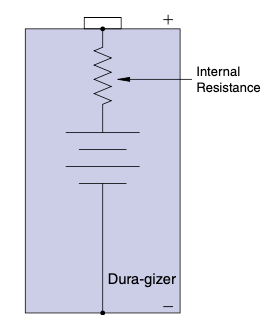
图 4.9 Dura-gizer;这才是真正坚固的电池!#
当电流加到负载上时,电压会在这个内部电阻上产生压降,就像分压规则所描述的那样。这个内部电阻就像外部的电阻一样发热,使电压源变热。如果电源没有补偿这种效应,你将会在输出端看到较低的电压。
What would cause a voltage source not to maintain the voltage output? Let me give you a hint: When put under load, a voltage source will heat up. So what creates heat? You got it: resistance. A voltage source has an internal resistance. A battery is a good example—see Figure 4.9.
FIGURE 4.9 The Dura-gizer; now that is one tough battery!#
As current is applied to the load, the voltage drop occurs across this internal resistance, just like the voltage divider rule says it will. This resistor inside heats up just like one on the outside does, making the voltage source warm. If the source doesn’t compensate for it, you will see less voltage at the output.
当元件不完美时的结论#
When Parts Aren’t Perfect Conclusion
元件就是不完美的。我见过电机轴承因为电容效应过早磨损,也见过电容器过热后顶部爆裂。真正最好的做法是不断查看数据手册。器件工程师尽力将器件的不足之处加以表征,并写进数据手册供你查阅。
Parts simply aren’t perfect. I have seen motor bearings wear out prematurely due to capacitive effects and have seen caps overheat and pop their tops. Truly the best thing to do is keep looking at the datasheet. Parts engineers do their best to characterize the deficiencies of the part and put it in the datasheet for you.
拇指规则(Thumb Rules)
永远要问:这个元件中的误差源是否足以引起我看到的现象?
如果误差源不足以构成问题,那就忘了它继续前进。
修复误差时,要么换个更好的元件,要么加强它,要么设计上规避。
电容随频率变化。
电感有内部电阻。
半导体有压降和热问题。
电压源有内部阻抗。
数据手册看得越多越好。
Always ask, is the error source in this component enough to cause the effect I am seeing?
If the source of error isn’t large enough to be an issue, forget about it and move on.
When fixing errors, get a better part, shore it up, or design it out.
Caps vary with frequency.
Inductors have internal resistance.
Semiconductors have voltage drops and heat issues.
Voltage sources have internal impedance.
You can’t study the datasheet too much.
稳健设计#
ROBUST DESIGN
大多数工程师希望设计得过于保守,给自己留足裕量,使用远高于实际所需规格的器件。通常管理者会说:“成本要更低,否则卖不出去”,或“你真的真的需要那个器件吗?”老实说,答案介于这两个极端之间。
Most engineers want to overdesign, give themselves plenty of headroom, and use parts that are double or triple the spec they need. Usually the manager is there saying,“It needs to cost less or it won’t sell,” or “Do you really, really need that part?” To be honest, the answer lies somewhere between these extremes.
你能容忍它吗?#
Can You Tolerate It?
让我们从一个完全泛泛而谈的说法开始,你可能会从一个发型尖锐、有点狡黠的人那儿听到这样一句话:“一个稳健的设计能很好地应对两件事:内部世界和外部世界。”你额头立刻写满困惑的表情。“这是什么意思?”你心想。让我来解释这段尖酸语言的含义。
内部世界是构成设计的所有元件。在任何生产过程中,这些元件的参数都会有所变化。你要问的是:“电路能否在这些元件的公差范围内正常工作?”如果答案是肯定的,那么设计在内部是稳健的。内部世界没问题。不过不要以为只有电子元件才有公差。这个道理通过实例讲述最合适。曾经我参与一个项目,我们用一个光学传感器检测皮带的运动。我们正确分析了传感器的公差,但在试产过程中我们发现皮带的不透明度有变化。如果光传感器处于其公差的高端,而皮带又是最透明的状态,那么传感器的信号就不会足够高,无法确保逻辑输入正确读取。
在大批量生产中,这类问题会表现为随机故障。这类故障被称为公差堆叠。当两个或多个元件的参数变化叠加,最终导致故障时,就是公差堆叠。这比单一元件的公差问题更难分析。预防这种故障最好的办法可能是借助仿真器。不过要小心:在你开始做公差分析之前,请确保你的仿真模型能准确代表使用了理想元件的设计。(关于仿真器的更多建议,见后续章节。)仿真器最大的优势就是能够在不制造一堆实物的情况下,模拟所有元件的公差变化并查看效果。这样你就可以调整设计和元件规格,从内部角度提高产品的稳健性。
而外部世界则是另一回事了。一个好的设计能够应对外部世界施加的各种影响。在电子领域,各种干扰都有可能破坏你的设计。我曾读过一篇文章,里面描述了一种“生锈锉刀测试”。工程师在测试完器件后,将其插入墙上的插座,同时插入自制测试夹具。该夹具由从 AC 中性线引出的导线连接到一把锉刀。火线一端剥了皮,然后他开始将它在这把旧锈锉刀上上下摩擦,火花四溅。[12] 如果电路能顺利通过这个测试,他就认为这东西没问题。这就是 EMI,也就是电磁干扰。这确实是一个庞大的主题,因此我专门为此写了一个章节。如果你迫不及待,直接跳到 第6章 吧!
你对外部世界的关注不应仅限于电气干扰。很多情况下,其他因素也会引发问题。例如,震动可能导致 PCB 上的走线断裂,焊点失效。湿度上升可能导致廉价 PCB 膨胀,从而造成机械变形和连接断裂。湿度也可能与杂质结合,在你不希望短路的电路上引起电气短路。温度对电子元件的影响尤其严重。你应当检查电路将会处于的温度范围,并与数据手册中的规格比较。不要忘记在分析中包含设备本身的工作温度。例如,功率器件在正常工作时本就会很热。如果你再把它放在 70ºC 的环境中,就很容易超过其最大温度规格。
那么你该如何从外部提升设计的稳健性呢?可以采取几种做法:
在我看来,最重要的是从基础设计上尽你所能,使其适应所处环境。通常对 PCB 布局做一些调整,比把它用各种屏蔽包起来更能抵御 EMI。更宽的走线可以抵抗机械变形,而几个位置合适的散热孔可以帮助管理温度。
接下来最重要的事情可能就是不断阅读你使用元件的数据手册。你越了解你使用的元件,就越能识别出可能破坏设计的问题。
第三种最全面的努力,就是测试、检查、测试、再测试你的设计。你需要重现电路将处于的各种环境,并观察它的表现。
此外,还可能出现一种情况,即问题来自内部设计的公差和所处环境效应的叠加。这类情况几乎无法预知,通常只能在实际使用过程中被发现。你唯一能做的是:找出预防它的方法,进行更改,并将其记录下来,以供将来类似设计参考。
我建议每位工程师和每个工程组都保留一份设计指南文档 [13],记录那些你在设计过程中发现的经验法则。不要只写下来,而要定期阅读它,这样你在每一次新设计时都能牢记它们。这本身就是一个非常强大的工具。几年前我接手一个工程团队。刚开始时,我们几乎每天都被叫去产线解决各种奇怪的问题,花在支持生产上的时间远远超过开发新产品。
我们开始专注于稳健设计原则,我实施的第一项措施就是编写设计指导文档。每次我们发现一个新的设计准则,就将它记录下来,并定期查看,确保在每一个新设计中都能落实。
在三年左右的时间里,这些紧急电话开始逐渐减少。我们从花超过 50% 的时间支持生产,减少到不到 10%。再过几年,支持生产的问题降到不到 1%。要知道,我们每天出货数万件产品,这可是一项巨大的成就。原本每天都会接到电话的我们,几个月都不会接到一次。即使偶尔出现问题,也几乎总能追溯到我们写过但没遵守的某条准则。最难的部分变成了在每次新设计时回头查看这些文档。既然如此,我建议你不要让你的设计准则文档太庞大。文档越大,你就越不愿去读。所以尽量控制在几页以内,毕竟它总有扩展的倾向。
为了量化外部世界可能带来的影响,很多标准文档被制定出来。虽然它们读起来很催眠(五分钟就能让你昏昏欲睡),但它们能让你真正了解你的设计将会受到哪些外部影响。我指的是像 IEEE 62.41(描述 EMI 世界)或 UL 991(描述如何保证控制系统的安全)这类文档。这类文档还有很多。花点时间研究你正在做的内容,看看是否有人写过相关文档。如果你的老板不理解你为什么要花时间阅读这些资料,就把下面这段话给他看:
老板,看起来工程师坐着读资料像是在摸鱼,但相信我, 这项投入能为你节省数百万的生产停工成本。 给你的工程师一个成功的机会,你一定不会后悔。
工程师,这不意味着你就只读不设计。我建议把这类研究控制在总设计时间的 10% 到 20%;如果你做的是从未做过的项目,可以适当翻倍。
这些资料在你彻夜难眠、思考自己设计哪里出了问题时尤其有用。我会把它们放在床边。这样我可以在睡前学习几分钟,也能顺便安然入睡。它们不仅能帮助你设计电路,还能治疗失眠!
Let’s start with a completely general off-the-wall statement that you might hear from someone with a sharpened, somewhat devilish hairdo:“A robust design handles two things well: the inside world and the outside world.” A look of consternation scrambles across your forehead.“What in the world does that mean?” you ask yourself. Let me proceed to enlighten you on this bit of pointy-speak.
The inside world is all the parts that make up the design. In any production pro- cess, these parts will vary in specification. The question to ask is,“Will the circuit operate correctly over the tolerance ranges of the parts?” If the answer is yes, the design is robust internally. The inside world is good to go. Don’t assume, how- ever, that only electronic components have tolerances. This point is best taught by example. In a design I worked on some time ago, we were using an optic sen- sor to detect the motion of a belt. We correctly analyzed the tolerance of the sensor, but as we began testing on a pilot run we discovered that the belt we were using varied in opacity. If the optic sensor was at the high end of its tolerance and the belt was at its most transparent, the signal from the sensor wouldn’t get high enough to guarantee that the logic input would read it correctly.
In a production run, a problem like this would appear as a random failure. This type of failure is known as a tolerance stack-up. It occurs when the stack- up (the additive effect of the variations) of two or more components combine to create a failure. It is more difficult to analyze than a single-component tol- erance issue. Probably the best way to preempt this type of failure is with the help of simulators. Take caution, though: Make sure that your simulation accu- rately represents the design with nominal perfect components before you start running tolerance analysis on it. (See the section on simulators for more sug- gestions.) The great thing about a simulator, though, is the ability to vary all the components over their tolerances and see the effects without building a whole bunch of parts. You can then adjust your design and component specs to increase the robustness of the product as far as the inside world is concerned.
Now the outside world is a different animal. A good design can handle the things the outside world throws at it. In the electronic realm all sorts of inter- ference can disrupt your design. I once read an article that described something called a rusty file test. After the engineer was done with the part, he would plug it into the wall and plug in a home-built test fixture next to it. It consisted of a wire from AC neutral connected to a file. The hot wire had a bare end that he would proceed to rub up and down the rusty old file, sparks flying everywhere. [12] If the circuit passed this test without a hitch, he figured it was good to go. This is known as EMI, or electromagnetic interference. It really is a whole topic unto itself, so I have dedicated a chapter to it. Skip ahead to Chapter 6 if you can’t handle the suspense!
Don’t limit your focus on the outside world to electrical interference. There are many cases where other things can cause a problem. Vibration, for example, can cause traces on a PCB to crack and solder joints to become faulty. Increased humidity can swell a cheap PCB, causing mechanical deformation and cracked connections. It can also combine with debris to create electrical shorts on cir- cuits that you don’t want shorted. Temperature can be particularly tough on electrical components. You should review the temperature range your circuit will be subject to and compare that to the specs in the datasheet. Don’t forget to include the operating temps of the device you are using in this analysis. For example, power components usually get pretty warm just operating. Toss them into a 70ºC ambient and you could easily push them over the max tem- perature spec.
How do you go about making your design robust externally? There are several approaches to take:
The most important, in my opinion, is doing everything you can in the fundamental design to get it to handle the environment it is in. Often a few changes to the PCB layout itself can make a circuit handle EMI better than putting all the shielding around it you can fit. Larger traces can combat mechanical deformation, and a few wellplaced holes can help manage temperatures.
Reading, reading, and rereading the datasheet for the component you are using is probably the next most important thing you can do. The more you know about the parts you are using, the better you will recognize things that might upset your design.
The third and most extensive effort that will help you is to test, check, test, and retest the design. You need to recreate the environments that it will be subject to and see what happens.
Now, to top it off, you can have a situation where the problem is a combination of the tolerance of the internal design and the environmental effects it is subject to. These situations are nearly impossible to predict and are often sim- ply discovered in the course of business. There is only one thing you can do about that: Figure out what is needed to prevent it, make the change, and docu- ment it for future use on similar designs.
I recommend that every engineer and engineering group keep a document of design guidelines [13] where you write down those rules of thumb that you dis- cover along the way. Don’t just write it down, but read it regularly to keep those things you have learned fresh as you do each new design. This alone can be a powerful tool. Some years back I took over an engineering group. When I first started managing it, it seemed like we were always being called to the produc- tion line for some weird problem or another. We spent more time chasing pro- blems than engineering new products.
We began to focus on robust design principles, and one of the first things I implemented was the design guideline documents. Every time we found a new design rule to follow, we wrote it down and referred to it regularly so that it would be implemented with each new design.
Over about a three-year period, those urgent calls to production began to drop off. We went from spending over 50% of our time in production support to spending less than 10%. A couple years after that, we were spending less than 1% of our time dealing with production problems. Considering that we were moving tens of thousands of products out per day, it was a great achievement. Months would go by without a call, where before we got calls every day. When problems did occur you could nearly always trace back to a guideline that we had written down and simply neglected to follow. The hard part became refer- ring back to those documents each time we created a new design. That being the case, I suggest you try not to let your guidelines get too large. The bigger these documents, the less likely you are to read through them. So try to keep them to a few pages, since they will have a tendency to grow a lot.
In an effort to quantify what the outside world can do, many standards have been written. They are some great yawners (meaning they will knock you out in about 5 minutes of reading); however, they can give you some real insight into what your design will be subject to from the outside in. I’m referring to documents like IEEE 62.41, which describes the world of EMI, or UL 991, which describes how to make a control safe. The list goes on and on. Do a little research into what you are working on and see if someone has written something about it. If your boss doesn’t understand the need for time to do this, show him this paragraph:
Boss, it might seem like nothing is getting done when the engineer is sitting there reading, but trust me, this effort can save you millions in production downtime, so give your engineer a chance to succeed and you will not regret it.
Engineer, this doesn’t mean that you should just read and never design any- thing; I would limit this research to about a 10 to 20% ratio of design versus research; double it if you are doing something you have never done before.
Reading these documents works particularly well if you are tossing and turning all night as you try to figure out what is wrong with your design. I would keep them by the side of my bed. That way I could learn some more for a few minutes and also get some sleep. They not only help with the design, they are a great cure for insomnia!
学会适应#
Learn to Adapt
你是否曾在完成一个产品设计之后,被要求做出某些更改,而你多么希望这些更改能在一开始就被告知?你是否曾说过:“如果你早点告诉我,现在加上这个功能的成本可以减半?”甚至你的老板还可能会说:“你怎么没做我让你做的事情?”(而你明明已经完全照他的意思做了)。让我告诉你一个秘密:大多数那些尖头发型的老板并不希望你失败。他们只是希望推出一个牛X的产品,以便他们能拿到更高的奖金。
他们没早点告诉你,是因为他们自己也不知道。他们只能尽力猜测客户想要什么,然后去满足它们。在老板的脑海中,他并没有说:“做某某产品”,他是说:“让这个产品成功。”随着公司不断追逐市场,新产品被开发、被更改、再被更改。我把这种情况称为“管理永远在追赶市场”(Management Always chasing the Market Around),简称 MAMA。(如果你想让别人记住一个观点,没有什么比缩写更有效的了。我预言未来某天,缩写会成为最主要的沟通方式,因为它高效!)正因如此,许多工程师在产品定义更改时都会感到困惑。
在消费电子产品领域,这种情况经常发生。当我在第一家公司接手工程组时,这种挫败感常常存在。随着我与公司各个设计师的合作,我发现可以提前预测这些更改并为之做准备。当你擅长这件事时,你可以轻松而快速地应对更改,还能以更快更低的成本开发出一系列派生产品。
Have you ever finished a product design after which some change was required that you desperately wished you had been told about at the beginning? Have you ever said,“If you had just told me sooner, this feature would have cost half as much to add on now?” You might even have had your boss say,“Why didn’t you do what I told you to do?” (when you did exactly what he or she wanted). I’ll let you in on a secret: Most of your pointy-haired bosses don’t want you to fail. They just want to ship a killer product so their bonus will be bigger.
They don’t tell you sooner because they don’t know sooner. They try to guess what the customers want and give it to them. In his mind your boss didn’t say, “Do such and such a product,” he said,“Make this product successful.” As companies chase the market around, new products are developed, changed, and changed again. I call this Management Always chasing the Market Around, or MAMA for short. (There is nothing like an acronym if you want a point to be remembered. I predict that some day in the far future acronyms will be the prime method of communication due to their efficiency!) Now, because of MAMA, many engineers experience consternation when their product definition changes.
In the world of consumer products, this is bound to happen often. When I took over the engineering group in the first company I worked for, this particular frustration was often felt. As I worked with the various designers in the company, I found that it was possible to anticipate these changes and prepare for them. When you get good at this, you can respond to changes easily and quickly, and you can also develop a number of derivative products quickly and inexpensively.
模块化设计#
Modular Design
为了预测更改,最重要的事情之一就是对你的设计进行模块化。在这方面,硬件设计师可以向软件设计师学习。优秀的软件工程师会构建可以反复使用的代码模块。但我常常看到硬件设计师每次新设计都从空白纸开始。
为了让模块化设计为你所用,你必须评估你正在设计的产品。是否有某些组件经常在各种设计中被替换或重复使用?哪些部分在你所有或大多数产品中是共通的?坐下来画大量方块图,然后问自己:“这是一个需要容易拆装的部分吗?”如果是,那它可能就是一个候选模块,可以放在独立的 PCB 上,或在 PCB 上划出独立的区域。例如,在一系列音响产品中,你可以将调谐器部分与前置放大器分开等等。(顺带一提,这种方式通常也能提升设计的稳健性。)
这种模块化方法的一个巨大优势是,它允许不同的工程师分别开发不同的模块,从而加速整个开发过程。它还允许你在不重做整个设计的前提下,升级或改进设计的某些部分。在我的领域中,最重要的是——它让你在老板突然决定不想在这个型号上加某个功能时,轻松做出更改。
不过,需要警告一句:你必须谨慎选择要模块化的部分。模块太多会导致你每一个出货产品的成本都上升。 确保你的选择是有意义的。
One of the most important things that you need to do to anticipate change is to modularize your designs. Here, hardware designers can take note from their counterparts in software design. Good software engineers build blocks of code that can be used and reused again and again. However, I often see hardware designers start with a clean sheet for every new design.
To make your modular design work for you, you must evaluate the products you are designing. Are there any components that are commonly removed and installed on various designs? What parts are common to all or most of your products? Sit down and draw lots of block diagrams and ask yourself,“Is this a part that needs to be easy to take on and off?” If it is, it might be a candidate for a separate PCB or a section of the PCB all to itself. In a line of stereo products, for example, you keep the tuner section separate from the pre-amp and so on. (As a side note, this often improves the robustness of a design as well.) A great advantage of this modular approach is the way it can accelerate the development process by using separate engineers on the various modules. It also allows you to upgrade or improve parts of the design without redoing the whole thing. Most important in my world and best of all, it makes it easy to change a feature when your boss decides he really didn’t want that there on this particular model.
One word of warning, however: You need to be careful what parts you choose to modularize. Too many modules can add up to extra cost in every product you ship. Make sure your choices make sense.
预测更改#
Anticipate Changes
尽量参与产品创建过程,这样你就能看到产品设计经历的各种演化阶段。通常,更改会是在这些演化路径上前后反复。不断问自己:“这个还能用在哪?我需要怎么改才能适应那里?”
注意哪些地方好像缺了一个部分。例如,假设你被要求设计一个带有一排 LED 的 PCB,如 图 4.10 所示。你说“好,没问题”,然后像 图 4.11 那样设计 PCB,并暂时不安装那个“缺失”的 LED。
别犹豫,告诉同事或老板你在做什么。他们在预测他们自己日后可能提出的更改时,可能会成为你的宝贵资源。最关键的是,每次都重新设计产品需要大量的工作量,但如果你在设计产品时能开发出有效的模块并预测更改,那么你就能比别人更快、更便宜地将产品推向市场。这种预见性设计的一个额外好处是,当你被要求开发一个类似产品时,你已经有所有必要的模块在手。你只需添加或移除某些功能即可搞定。最后也是最棒的一点:MAMA 将不再逼疯你!
图 4.10 管理层想要的一排 LED。#
图 4.11 实际放入的一排 LED。#
Try to get involved in the creation process so that you can see various phases of evolution the product design has gone through. Often, changes that are made will be back or forth on this evolutionary path. Keep asking yourself,“Where else could this be used? How would I change it to work there?” Look for places where a part seems to be missing. For example, say that you are asked to make a PCB with a row of LEDs that look like Figure 4.10. Say“Great, no problem,” and then create a PCB with this row of LEDs, as shown in Figure 4.11, and simply do not install the missing one for now. Don’t hesitate to tell your coworkers or boss what you are doing. They can be a great asset in anticipating changes they might come up with later. The bottom line is that it takes a tremendous amount of work to redesign every product every time, but if you can develop effective modules and anticipate changes when you are engineering the product, you can bring things to market faster and cheaper than anyone else. A nice benefit of this type of anticipative design is that when you are asked to develop a similar product, you have all the pieces in place. You simply add or subtract the required feature and are done with it. Finally, best of all, MAMA will not drive you berserk!
FIGURE 4.10 Row of LEDs management wants.#
FIGURE 4.11 Row of LEDs you actually put in.#
最后一个警告#
One Last Word of Caution
采取这种设计理念当然是好事,但也可能走得太远。不要让你的设计为了追求通用性而导致产品无法及时上市,或者因加入太多可选功能而使产品不再具备商业可行性。记住,有些你提前设计好的选项,也许永远都不会被使用。因此,明智地选择吧,年轻的绝地武士。 [14]
It is possible to go too far with this philosophy. Don’t try to make your design so universal that it comes at the expense of getting the product to market or adds so much cost for all the options that it is no longer viable. Remember, there is also a chance you will never use the option you built in, so choose wisely, young Jedi. [14]
拇指规则(Thumb Rules)
阅读数据手册。
考虑元件公差。
了解使用环境。
测试、检查、再测试。
编写你自己的拇指规则或设计准则清单。
查阅与你产品相关的已有标准或指导文件。
MAMA 可能令人沮丧。
模块化你的设计。
预测可能的更改。
不要走得太远。
Read the datasheet.
Consider tolerances.
Know the environment.
Test, check, and retest.
Make your own list of Thumb Rules or design guidelines.
Do research on standards or guidelines that exist for your product.
MAMA can be frustrating.
Modularize the design.
Anticipate changes.
Don’t go too far.
我最喜欢的一些电路#
SOME OF MY FAVORITE CIRCUITS
每个工程师都有自己最喜欢的一批电路,我也不例外。市面上有大量电路宝典,教你如何实现各种酷炫功能。它们太多了,以至于你可能一直在查阅它们,而永远做不出任何实际成果。我建议你自己积累一些最基础、最喜欢的电路,对它们了然于心、直觉掌握。这其实是我们在本书开头所讲的“乐高哲学”的自然延伸。下面是我最喜欢的一些电路,除了前面章节中作为示例出现的电路以外。它们之所以是好例子,就是因为它们非常实用。
Every engineer has their favorite batch of circuits, and I’m no exception. There are tons of circuit cookbooks out there that show how to implement no end of cool features. There are so many that you could spend all your time searching them and never getting anything done. I suggest you develop your own favorite basic circuits that you know well and intuitively understand. This is simply an extension of the Lego philosophy that we discussed way back at the beginning of the book. Here are a few of my favorites. These are in addition to all the cir- cuits I have used as examples up to this point. One reason they make such good examples is that they are so useful.
混合达林顿对#
Hybrid Darlington Pair
一个很酷的应用笔记:使用两个晶体管来切换一个由 NPN 控制的 Vcc PNP 电平信号。
图 4.12 展示了一个实用电路,它可以用较低电压来切换较高电压。例如,你有一个输出为 5V 的微控制器,但你需要驱动一个 12V 的负载。由于某些你无法更改的原因,你必须切换 Vcc 端。在这个电路中,你使用 5V 信号打开第一个晶体管,它随后激活另一个晶体管,从而将较高电压切换到负载上。
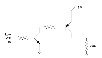
图 4.12 NPN 控制的 Vcc PNP。#
这个电路之所以有效,是因为晶体管是电流驱动的;当你切断流向 PNP 晶体管的电流时,它就会关闭,无论电压如何。另一个优点是,该电路具有类似达林顿对的特性,但没有其缺点之一。你不需要向输入端提供大量电流即可切换输出,而且与传统达林顿对不同的是,输出端的电压降要小得多。你不需要处理输出端串联的两个基极结。如果你仍然不明白,不妨用一点 ISA [15] 来分析。
Cool application note: using two transistors to switch a signal level Vcc PNP switched by NPN.
Figure 4.12 shows a handy circuit that switches a higher-level voltage with a lower-level one. Say, for example, you have a micro with a 5 V output and you need to drive a 12 V load. For a reason you can’t change, you have to switch the Vcc leg. In this circuit you turn on one transistor with a 5 V signal, which in turn activates the other transistor, switching the higher voltage to the load.
FIGURE 4.12 Vcc PNP switched by NPN.#
This works because the transistors are current driven; when you shut off the current flow to the PNP transistor, it shuts off regardless of the voltage. Another plus is that this circuit has Darlington-like properties without one of the downsides. You won’t need a lot of current to the input to switch the out- put and, unlike a traditional Darlington pair, the voltage drop across the out- put is much smaller. You don’t have two series base junctions to contend with at the output. If you still don’t follow, try a little ISA [15] on it.
直流电平转换器#
DC Level Shifter
这实际上是我们之前学过的高通滤波器,但做了一点变化,如 图 4.13 所示。不是将电阻接地,而是连接到一个参考电压。由于直流的频率为零,只有 交流 成分会通过,在这个过程中,一个直流偏置会被施加到信号上。请确保你所选择的电容和电阻不会使你想要的信号被过度衰减。
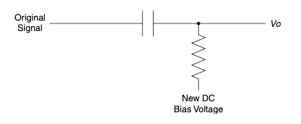
图 4.13 改变交流信号上的直流偏置。#
This is really the high-pass filter that we have already studied but with a slight twist, as shown in Figure 4.13. Instead of ground, we hook the resistor to a refer- ence voltage. Since DC has a frequency of zero, only the AC component will pass and in the process a DC bias will be applied to the signal. Make sure that you don’t size the cap and resistor so that the signal you want is attenuated.
FIGURE 4.13 Change the DC bias on an AC signal.#
虚地#
Virtual Ground
使用电压分压器作为参考,运算放大器就变成了一个电压源,其输出等于分压器上的电压——见 图 4.14。当你想用单电源电路处理 交流 信号时,这会非常有用。
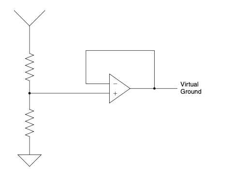
图 4.14 在你想要的电平上创建一个“地”。#
Using the voltage divider as a reference, the op-amp becomes a voltage source with the output matching the voltage at the divider—see Figure 4.14. This can be very useful when you are trying to handle AC signals with only a single-ended supply circuit.
FIGURE 4.14 Create a“ground” at any level you want.#
电压跟随器#
Voltage Follower
如 图 4.15 所示,当你试图测量一个容易受负载影响的信号时,这个电路非常有用。Vi = Vo,但最重要的是,由于运算放大器的缓冲作用,Vi 完全没有被加载。
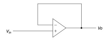
图 4.15 电压跟随器。#
As Figure 4.15 shows, this one is mighty useful when you’re trying to measure a signal that is easily affected by load. Vi= Vo, but, best of all, Vi isn’t loaded at all, thanks to the buffering effect of the op-amp.
FIGURE 4.15 Voltage follower.#
仅交流放大器#
AC-Only Amplifier
图 4.16 展示了另一个优秀电路,它在用单电源放大 交流 信号时表现良好。它还有一个好处:不会放大任何直流信号成分,从而避免诸如直流偏移等问题使你的信号上轨。这是因为反馈电路中的电容。由于电容只传递 交流 电流,直流信号会视该点为断开。当接地电阻断开时,运算放大器就像前一个电路中的电压跟随器一样工作。
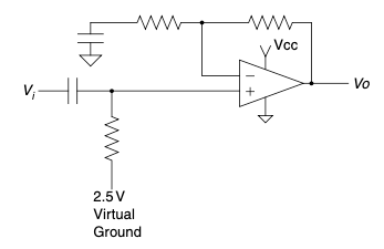
图 4.16 仅交流放大器。#
Figure 4.16 shows another great circuit that works nicely in amplifying AC signals with a single-ended supply. It also has the benefit of not amplifying any DC signal components, keeping things like DC offsets from making your signal rail. This happens because of the cap in the feedback circuit. Since the cap only passes AC current, DC signals see that point as disconnected. When the resistor to ground is disconnected, the op-amp acts like the voltage follower in the previous circuit.
FIGURE 4.16 AC-only amplifier.#
反相振荡器#
Inverter Oscillator
多年前我在一本数据手册的最后看到这个电路;我记得那是摩托罗拉的逻辑数据手册。那时候还没有互联网,你必须真正翻页去找这些东西!这个电路的工作原理基于施密特触发器反相器的输入具有迟滞特性(图 4.17)。这使得输出会保持在高或低电平,直到输入端电容充电到触发反相器的阈值电压。输出翻转,一切反向,周而复始地重复。如果你在充放电路径中加入一些二极管,可以影响输出的占空比。
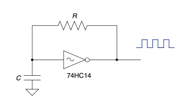
图 4.17 施密特触发振荡器。#
I saw this in the back of a data book years ago; I think it was a Motorola logic data book. This was way back before the Internet. You used to have to turn actual pages to find this stuff! The way it works is based on the fact that the Schmidt trigger inverter has hysteresis built into the input (Figure 4.17). This makes the output stick at a high or low level until the cap on the input charges to the threshold voltage that trips the inverter. Out- put flips and everything goes in the other direction, repeating indefinitely. Adding some diodes to the charge and discharge path can affect the duty cycle of the output.
FIGURE 4.17 Schmidt trigger oscillator.#
恒流源#
Constant Current Source
利用负反馈,运算放大器试图保持 R 输入上的压降不变。即使负载电阻发生变化,R 输入上的压降仍保持一致。根据欧姆定律,保持 R 和 V 不变,也就意味着电流保持不变——见 图 4.18。不过请记住,这种电流控制是有操作极限的;输出电压的摆动范围有限,无法无限补偿负载变化。一旦超出这些极限,就无法再保持恒流调节。
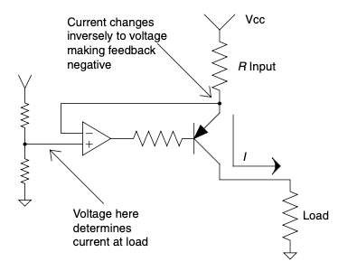
图 4.18 电压控制的恒流源。#
Using negative feedback, the op-amp tries to maintain the voltage drop across R input. Even if the resistance of the load changes, the drop across R input stays the same. According to Ohm’s Law, keeping R and V the same will keep current the same, too—see Figure 4.18. Remember, though, this current control has operational limits; it can only swing the output voltage so far to compensate for load variance. Once these limits are reached, the current regulation can no longer exist.
FIGURE 4.18 Voltage-controlled constant current source.#
拥有你自己的——这里有几个示例#
GET YOUR OWN—HERE ARE A FEW
我只有几个最喜欢的电路概念。拥有属于你自己的,并且熟知它们。深入了解几个电路概念,比浅尝辄止地知道成千上万个电路要更有用。
按照这个建议,第一版的几位读者寄来了他们喜欢的一些电路。下面不多说,直接呈现给大家。
Steve Petersen 送来了 图 4.19 中所示的电路,他说这个电路派对上玩很有趣,还可以加上一个延时电路,当别人拿起装有该电路的有趣装置时,会被吓一跳 [16]。
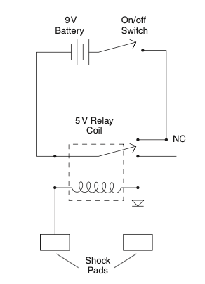
图 4.19 玩具电击器电路。#
Travis Hayes 送来了 图 4.20 中的一个精巧小电路图,它使用了我列表中的反相振荡器来驱动一个电压倍增电路。他说这是为他使用的液晶显示器获得更高电压的一个非常灵巧且廉价的方法。我必须同意!
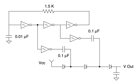
图 4.20 反相器驱动的电压倍增器。#
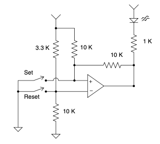
图 4.21 触发器存储运放电路。#
Alan Tyger 可能和我一样是运放的铁粉。他寄来了 图 4.21 中的电路图,使用了这样的器件来存储一条信息。
Michael Covington [17] 送来了 图 4.22 中的酷炫电路;它将遥控的乐趣和激光指示器结合起来。555 定时器作为存储单元(和 Alan 的电路类似),但这个电路额外增加了使用激光控制的功能。多酷啊!我不知道哪个工程师不喜欢激光,我敢肯定他们回家看电视时都得控制遥控器。
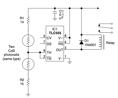
用激光笔照射任一光电池即可切换状态。供电电压不敏感(根据继电器要求为 5 到 15 V)。注:为平衡光电池性能并在强光条件下获得更好表现,可省去 R1 或 R2 中的一个(但不能同时省去)。#
图 4.22 激光光控开关。
Mike Angeli 送来了 图 4.23 中的酷炫电路。他说用它结合电位器反馈来定位负载(因此需要高阻抗)。
Sam Nay 送来了 图 4.24 中的电路,他说他一直对无线上传输数据的能力感到着迷。我敢打赌他接上了刚才看到的激光控制开关。另外,我还知道一个秘密电路,虽然不便透露,但它用的光学电路变体与这个类似,可用于生物识别采集。真希望我能给你看看那个,不是吗?
最后,Mourly Thov 送来了 图 4.25 中的电路。他说这是一种巧妙的方法用来改变直流电压(并具有一定的功率容量,这可能是 Travis 电路中的一个问题),所以如果你需要一个可以提供一定电流的不同电压,不妨试试这种方案。
最后,我要说的是,通过与这些工程师的交流,我觉得他们都属于 RSP [18] 类。或者说,可能只是因为他们给我发了邮件,而且非常喜欢本书第一版。无论如何,我感谢他们的投稿,并完全免责,任何这些电路能否实际工作均由你自负。希望它们能带给你好运,帮你填满一本你自己的最爱电路笔记。
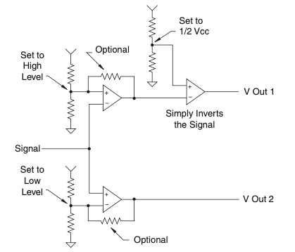
图 4.23 激光光控开关。#
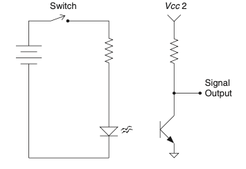
图 4.24 激光光控开关。#
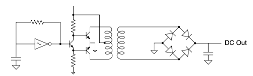
图 4.25 激光光控开关。#
经验法则
保持你自己的酷炫电路手册。
熟悉它们。
I have just a few favorite circuit concepts. Get your own and know them well. You will be better served knowing a few circuit concepts inside-out than know- ing thousands superficially.
Following this advice, several readers of the first edition sent in some of their favorite circuits. Without further ado, they are presented next. Steve Petersen sent in the circuit shown in Figure 4.19, saying something about being fun for parties and the potential to add a delay circuit to really surprise someone [16] when they picked up whatever interesting device the circuit was embedded in.
FIGURE 4.19 Toy shocker circuit.#
Travis Hayes sent in the diagram of a sleek little circuit, as shown in Figure 4.20, that uses the inverter oscillator from my list to drive a voltage doubler circuit. He said it was a pretty slick and inexpensive way to get a higher voltage for an LCD he was using. I’d have to agree!
FIGURE 4.20 Inverter-driven voltage doubler.#
FIGURE 4.21 Flip-flop memory op-amp.#
Alan Tyger just might be as big a fan of op-amps as I am. He sent in the circuit diagram shown in Figure 4.21 ; it uses just such a device to store a piece of information.
Michael Covington [17] sent in the cool circuit shown in Figure 4.22; it combines the fun of remote controls with a laser pointer. The 555 acts as a memory cell (not unlike Alan’s circuit), but this one has the added bonus that you use a laser to control it. How cool is that! I don’t know any engineer who doesn’t like lasers, and I’m pretty sure they all have to control the remote when they are home watching TV.
Hit one or the other photocell with a laser pointer to change states. Supply voltage is not critical (5 to 15 V depending on requirements of relay). Note: Either R1 or R2 (not both) can be omitted to make up for imbalance between the photocells and provide better performance in bright-light conditions.#
FIGURE 4.22 Laser light switch.
Mike Angeli sent in this cool circuit in Figure 4.23. He said he used it to posi- tion a load using a potentiometer feedback (thus the high-impedance requirement).
Sam Nay sent in the circuit shown in Figure 4.24, saying he was always fascinated by the ability to transmit data without wires. I’ll bet he hooks up the laser-controlled switch that we saw just moment ago. Also, I happen to know of a secret circuit that I am not at liberty to disclose that uses a variation of optical circuits not that different from this one to take biometric readings. Bet you wish I could show you that one, don’t you!?
Finally, Mourly Thov sent in the circuit shown in Figure 4.25. He said he just thought it was a slick way to change the DC voltage (and have some power capacity, which could be an issue with the one Travis sent in), so if you find yourself in need of a different voltage that can move some current, try an idea like this one.
On a final note, I have to say that from my communication with these engineers, I think they all fall in the RSP [18] category. Then again, maybe that is just because they emailed me and really liked the first edition of this book. Either way, I thank them for their submissions and completely absolve myself from any responsibility for these circuits actually working. I hope they bring you luck and help you to fill up a notebook with your favorite circuits.
FIGURE 4.23 Laser light switch.#
FIGURE 4.24 Laser light switch.#
FIGURE 4.25 Laser light switch.#
Thumb Rules
Keep your own cookbook of cool circuits.
Learn them well.
电源#
POWER SUPPLIES
无论你用电子技术做什么,都需要电力来完成。了解电源的基础知识非常有用,因为在你的职业生涯中几乎肯定会遇到它们。
Whatever you do with electronics, you are going to need power to accomplish it. It will be useful to understand the basics of power supplies, since you are nearly guaranteed to deal with them at some point in your career.
电压为王,宝贝!#
It’s All About the Voltage, Baby!
如今大多数设备都希望保持电压恒定。这意味着电流可以根据需要变化。在电力领域,尤其是涉及无处不在的集成电路(IC)时,你常常得不到完全想要的电压。
大量产品使用墙壁插座的120 V交流电(AC)供电。另一大批产品使用可从插座充电的电池,还有一些大量使用可以在大型超市买到的电池。问问自己,去年圣诞节你买了多少电池?
问题是,现在大多数集成电路需要5V、3.3V甚至1.5V直流电(DC)。这离120V相差甚远,而且绝不是交流电!这就需要电源供应器。电源分为两种类型:线性电源和开关电源。
Most devices today want to keep the voltage constant. This means that current can vary as needed. In the world of power, particularly as it relates to the ubiquitous IC, it often seems that you never have the exact voltage you want. A huge number of products run off 120 V AC out of a wall socket. Another huge group runs off batteries that are charged from those wall sockets, and another significant number runs off batteries that you can buy by the caseload at any super-duper-mart. Just ask yourself, how many batteries did you buy last Christmas? The problem is that most ICs these days want 5, 3.3, or even 1.5 V DC. This is nowhere near 120 V, and definitely not AC! Enter the power supply. They come in two flavors, linear and switcher.
线性电源#
Linear Power Supplies
交流电(AC)是主角!它无处不在。虽然现在看似世界运行在电池上,但交流电仍占据主导地位。在爱迪生和特斯拉争论我们应该使用哪种电力分配方式的时候,我敢打赌他们根本没想到未来100年电力领域会发生如此多的集成变革。[19]
他们知道的其中一件事是变压器。变压器的基础是交流电。将交流电输入变压器一端,根据绕组比率,你会从另一端得到交流电。因此,将120V交流电输入一个10比1的变压器,输出将是12V交流电(扣除绕组电阻产生的热损失)。
基本的变压器结构非常简单,就是绕在铁芯上的线圈。这使它非常坚固。变压器是改变交流信号电压的完美方法。它们被用来将电压大幅提升,以减少长距离线路上的损失,然后再将电压降低到安全的水平供家庭使用。
之后,数以百万计的产品中电压被进一步降低,但此时输出仍为交流信号。然而,大多数芯片需要直流信号,那么接下来会怎样?它要经过整流器。常用的有两种:桥式整流器,如 图 4.26 所示;中心抽头整流器,如 图 4.27 所示。注意后者少用了两个二极管并多接了一根变压器线,但整流输出相同。还注意输出的“波纹”吗?
此时无论哪种整流器的输出仍然“波纹”过大,不适合敏感的直流电路使用。下一步是在输出端加一个大容量滤波电容,平滑波纹,如 图 4.28 所示。
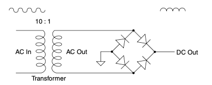
图 4.26 桥式整流器。#
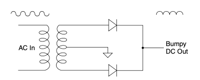
图 4.27 中心抽头桥式整流器。#
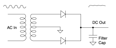
图 4.28 带电容滤波的中心抽头桥式整流器。#
现在要了解输出阻抗的原理了。每个电源都有输出阻抗。你从电路中拉取的电流越大,输出阻抗问题越明显。记住欧姆定律:电流通过阻抗时,阻抗两端的电压降会增加。这意味着随着负载增加,输出电压会下降。更复杂的是,电路中的整流器会导致负载增加时输出的纹波电压也增加。
所以,两个主要因素影响输出电压:输入电压(大多数交流电路的输入电压可以变化10%以上)和所拉电流大小,这两者都会导致电压降和电压纹波增加。
了解这些很重要,因为接下来电压进入下一部分电路,称为稳压器。稳压器会调整输出以维持负载和输入电压变化时的恒定电压。
线性稳压器通常内置电压参考(如稳压二极管 [20]),该参考工作电流小,不受负载影响。它利用此参考和负反馈回路控制内部晶体管或其他元件,保持输出电压恒定。这就提供了IC所需的稳定直流电压。墙壁电源到稳压输出的整个电路如 图 4.29 所示。
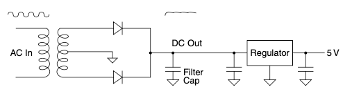
图 4.29 典型线性稳压电源。#
关于线性稳压器,有几点重要的知识:
它们有最低输入电压。如果输入电压降到低于此值(如前述情况),输出电压将失去调节。此时,芯片的电源可能出现纹波。如果纹波足够小,你可能察觉不到;但若电路增益高容易拾取交流噪声,应首先检查电源。
另一个常被忽视的重要参数是稳压器的功率额定。即使带散热片,稳压器也有最大可承受功率。稳压器消耗的功率是电流乘以稳压器两端的电压降,而非输出电压!数据手册中还有很多参数需要检查,但这些是最重要且常被忽视的。请优先检查。
线性稳压器适用于任何直流输入直流输出的场合。它们大多表现良好,且结构简单、稳健。能用线性稳压器时尽量用。这种技术在某些应用中没有问题,但如果你需要更高效率或更少发热,应考虑使用开关电源。
AC rules! It is everywhere. It might seem like the world runs on batteries these days, but AC still has the majority foothold. Back when Edison and Tesla argued over what type of electrical power distribution we should have, I’ll bet they had no idea of the type of integration that would occur in the world of electricity over the next 100 years. [19] One thing they did know about was the transformer. The basis of the transformer is AC current. Put AC into one side of the transformer and, depending on the ratio of windings, you get AC out the other side. So, put 120 V AC into a 10- to-1 ratio transformer and you will get 12 V AC out (minus heat losses due to the resistance of the windings).
The basic transformer is a very simple design. It is coils of wire on hunks of metal. That makes it robust. A transformer is a perfectly acceptable way to change the voltage of an AC signal. Transformers are used to jack the voltage way up to minimize losses over long wires, and then they are used again to bring the voltage back down to something safer to bring into your house.
They further knock the voltage down again in millions of products, but at that point they still output an AC signal. However, most of our chips want a DC signal, so what happens next? It goes through a rectifier. There are two commonly used options: a bridge rectifier, shown in Figure 4.26, and a center tap rectifier, shown in Figure 4.27. Note how this uses two fewer diodes and another wire to the transformer, yet the rectified output is the same. Notice the“bumpy” DC output?
The output at this point of either rectifier is still too“bumpy” to be of much use to our sensitive DC circuits. The next step is to add a large filter capacitor to smooth out the bumps, as shown in Figure 4.28.
FIGURE 4.26 Bridge rectifier.#
FIGURE 4.27 Center tap bridge rectifier.#
FIGURE 4.28 Center tap bridge rectifier with cap filter.#
It’s time to learn the principle of output impedance. Every power supply has it. The more current you pull out of the circuit, the bigger issue the output impe- dance is. Remember that Ohm’s Law says that as current increases through an impedance, the voltage drop across it increases. This means that the voltage at the output will drop as load increases. To further complicate things, the rectifier in this circuit will contribute to an increased ripple voltage on the output as load increases.
So, two important things affect the voltage on the output of this circuit: the voltage going into it (which on most AC circuits can vary 10% or more) and the amount of current being drawn, increasing voltage drop and voltage ripple.
This is important to know as we feed this into the next part of the circuit, called a regulator. The regulator is a part that adjusts its output to maintain a constant voltage in the face of a changing load and a changing input voltage. A linear regulator typically has a voltage reference (like a zener [20] diode) inside it running on a small current that isn’t disrupted by the load. It uses this reference and a negative feedback loop to control a transistor or other part inside to maintain a constant voltage at the output. This gets you to the nice DC voltage that your IC wants. The whole circuit from the wall looks some- thing like Figure 4.29.
FIGURE 4.29 Typical linear regulated power supply.#
There are a couple of important things to know about linear regulators. They have a minimum input voltage. If the input voltage falls below this rating due to circumstances described earlier, the output will fall out of regulation. If this happens you can get ripple on the power supply to your chip. If it is small enough, you might never notice it, but if you have some high-gain circuits picking up AC noise, check out the power supply for problems first.
The other often-overlooked important spec is the power rating of the regulator. A regulator can only handle so much power, even with a heat sink. The power being dissipated by the regulator is the current times the voltage drop across the regulator, not the voltage at the output! There are many other specs you should review in the datasheet, but these are the most important and often overlooked. Check them first. You can use linear regulators in any DC-in, DC-out situation. They will do very well in most cases and, to top that, they are very simple and robust circuits. Use them whenever you can. There is nothing wrong with this technology in certain applications, but if you need more efficiency or maybe less heat, you should consider a switcher.
开关电源#
Switchers
一种调节器和电源类型,正在迅速取代较老的线性设计,被称为开关电源。顾名思义,开关电源通过切换电流(或电压)的开关来调节负载的电力。在本书中,我们将重点关注电流控制方法。(不过别忘了,电流和电压总是密不可分的,正如欧姆定律所证明的。)这种电源的秘密是电感器,而理解电感器的关键在于电流。就像电容器想保持其两端电压恒定一样,电感器也想保持其流过的电流恒定。
A type of regulator and power supply rapidly gaining footholds over the older, linear designs is called a switcher. As implied by the name, the switcher regulates power to a load by switching current (or voltage) on and off. In this book we will focus on the current method. (Don’t forget, however, that current and voltage are invariably linked, as Ohm proved so well.) The secret to these sup- plies is the inductor, and the secret to understanding an inductor for me is to think in terms of current. In the same way a capacitor wants to keep voltage across it constant, an inductor wants to keep the current flowing through it constant as well.
直流是我们的起点#
DC IS WHAT WE START WITH
开关电源是直流转直流转换器。即使是带有交流输入的开关电源,也会先通过整流电路生成直流母线电压,然后再实施开关控制。
你会看到开关电源取代我们之前电路中仅作为稳压器的部分,工作在已经经过变压器降压的直流母线电压上。你也会看到直接使用整流后的交流线路电压,一步完成从120V降到5V并稳压的开关电源。
我所知道的最基本的电流开关电源是降压转换器(buck转换器)。降压转换器可以将较高的直流电压转换为较低电压。图4.30显示了一个降压电路的核心。
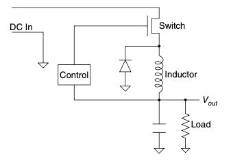
图 4.30 基本开关降压转换器。#
首先,识别四个主要部分:电感器、开关、二极管和负载。
Switching power supplies are DC-to-DC converters. Even those that have an AC input create a DC bus, using a rectifier circuit before implementing a switcher. You will see switchers replacing just the regulator in our earlier circuit working off a DC bus voltage that has already been stepped down by a transformer. You will also see switchers that use rectified voltage right off the AC line and drop and regulate all in one step from 120 V down to 5 V.
The most basic current-switching supply I know of is the buck converter. A buck converter will knock a DC voltage from a higher level to a lower level. Figure 4.30 shows the heart of a buck circuit.
FIGURE 4.30 Basic switching buck converter.#
First, let’s identify the four main parts: the inductor, the switch, the diode, and the load.
切换开关#
FLIP THE SWITCH
我们从负载开始,向后推导。首先,开关电源喜欢有负载。没有负载会出现奇怪的现象,稍后详述。负载想要的是恒定电压(在大多数情况下)。如果我没记错欧姆定律,可以通过控制负载(即电阻)上的电流来控制其两端的电压,所以让我们来考虑电路中的电流流动。
我们从开关闭合开始。开关闭合时,电流通过电感器流向负载。电流会根据电感的时间常数和负载阻抗上升。电流上升时,负载两端的电压也上升。现在假设电路监测负载电压,一旦电压过高,就打开开关。
那么发生了什么?首先记住这一点。就像电容器抗拒电压变化一样,电感器抗拒电流变化。当开关打开时,电感器试图保持电流流动。如果电流无路可走,随着磁场崩塌,电感两端会产生高压。实际上,在时间=0时,这电压是无限大或未定义的,随你喜欢。但在此电路中,由于二极管和负载,这种情况不会发生。
电流流入负载,原因在于二极管。这样理解:电流想继续从电感流出并流入另一端。如果没有二极管,这电流无路可走。但有了二极管,电流就被推过负载。因此,开关打开后,电流仍然流向负载。电流从开关打开时的电流水平开始(记住,电感器想保持电流不变!),然后逐渐衰减。电流降低时,电压也下降。当然,我们仍有电路监测负载电压,当电压过低时,开关再次闭合。
Voilà,过程重新开始。我意识到两件重要的事。第一,这个控制电路可以用简单的比较器和一点滞后实现。当然,这意味着开关频率由电感和负载阻抗决定,这可能是优点也可能不是。第二,当开机时,电路会猛地关闭开关并长时间保持,直到电流在电路中累积。你开始明白为什么开关电源需要负载了吗?
幸运的是,比我聪明得多的人已经解决了这些问题。这就是你开始学习开关电源时会听到“软启动”和“内置PWM”等术语的原因。
Let’s start with the load and work our way backward. To begin with, switching supplies like to have a load. Without a load funny things can happen, but more on that later. What the load wants (in most cases) is a constant voltage. If I remember Ohm’s Law correctly, one can control the voltage across a resistor (i.e., load) by controlling the current through it, so let’s consider the flow of current in this circuit. We will begin with the switch closed. With the switch closed, current will flow through the inductor into the load. The current will rise based on the time constant of the inductor and the impedance of the load. Since the current rises, so does the voltage across the load. Assume now that we have a circuit that is monitoring the voltage across the load, and as soon as it gets too high it opens the switch.
Now what happens? First, remember this fact. Just as a capacitor resists a change in voltage, an inductor resists a change in current. When the switch opens, the inductor tries to keep the current flowing. If there is nowhere for it to go, you will see a large voltage develop across the inductor as the magnetic field collapses. In fact, at time = 0 the value of this voltage is infinite or undefined, whichever suits you. That doesn’t happen in this case due to the diode and the load.
The current flows into the load, and the reason it does so is because of the diode. Consider it this way: Current wants to keep flowing out of the inductor and into the other side of the inductor. Without the diode there would not be a path for this current to follow. However, with the diode, this current is pushed through the load. So now the switch is open, and current is still flowing into the load. This current starts out at the same level it was when the switch opened (an inductor wants to keep current the same, remember!) and it decays from there. As the current falls, so does the voltage. Of course we still have a circuit monitoring the voltage across the load, and as soon as it gets too low, it closes the switch again.
Voilà, the process starts all over. There are two important things I noticed once the pieces fell into place in my head. The first is that this control circuit I just described can be implemented with a simple comparator and a little hysteresis. Of course, that would lead to the frequency of the switcher being determined by the value of the inductor and the impedance of the load. That may or may not be a desirable trait. The other thing I realized was that when you first turned it on, the circuit would want to slam the switch shut and keep it there for a long time while current builds up in the circuit. Are you beginning to see why switchers need a load?
Luckily, others much smarter than I have dealt with these problems already. That is why you hear terms like soft start and built-in PWM when you start study- ing switching supplies.
一些最后的想法#
Some Final Thoughts
由于开关电源的设计、稳定性以及电感规格较为复杂、技术性强且繁琐,各种公司纷纷推出了设计指南甚至网页设计平台,帮助你构建开关电源,我强烈建议你利用这些资源。
如今,你会发现所有的核心元件、开关元件和反馈部分都集成在一个小巧的芯片中,[21] 使设计紧凑且体积小。你可以制造升压型开关电源,也可以制造降压型,还有双向型,但归根结底它们都依赖电感想保持电流恒定的特性。更深入的内容留待另一本书讲解。
开关电源最好的地方是用相对较少的铜线就能达到很高的效率(意味着更少的发热)。原因是电感中电流的衰减速率取决于电感大小,但如果开关频率更高,平均电流和平均电压依然保持。因此,尤其是大电流低电压应用,你可以用更少的铜线。效率高是因为相比等效变压器设计,小电感中加热铜线的功率损耗要少得多。
然而,这一切是有代价的。开关电源因其高频噪声而闻名,常常干扰许多敏感的模拟设计。但现在谁还关心模拟电路呢,对吧?
Since designing switching supplies, getting them stable, and dealing with the inductor specs can be a bit demanding, technical, and tedious, all sorts of industry help has sprung up in the effort of various companies trying to get you to use their parts. You will find design guides and even Web design plat- forms out there to help you build a switcher for your design, and I highly sug- gest you take advantage of them.
These days you will often find all the brains, switching components, and feed- back parts in one cute little package, [21] making the design nicely compact and small. You can make switchers that boost voltage as well as the buck versions, and some that even go both ways, but ultimately they rely on the fact that the inductor wants to keep current flow the same. We will save the more in-depth review for another book on another day.
The best thing about switching supplies is the fact you can get by with relatively little copper and attain very high efficiency (meaning less heat). The reason for this is that the decay rate of the current in the inductor depends on the size of it, but if you switch it faster, the average current and thus the average voltage is still maintained. So you can get by with much less copper, especially for larger current draws at low voltages. The efficiency is good because much less power is spent heating the copper in the small inductor than in an equivalent transformer design. However, all this comes at a price. Switchers are known for their high-frequency noise that has dis- rupted many a sensitive analog design. But who cares about analog anymore, right?
经验法则(Thumb Rules)
确保纹波电压最低谷不低于稳压器的最低输入电压。
在交流输入信号的±15%范围内检查电源性能。
线性稳压器的热量/功率损耗基于输入与输出之间的电压差乘以电流。
开关电源利用电感即使开关断开也想保持电流流动的特性。
开关电源效率更高,发热更少,但通常调试更麻烦。
线性电源在电磁干扰(EMI)方面非常安静。
开关电源在电磁干扰方面通常噪声很大。
开关电源需要最低负载才能正常工作。
Make sure the lowest dip on the ripple voltage doesn’t go below the minimum input of the regulator.
Check your supply at ±15% of the AC input signal.
Linear regulators dissipate heat/power based on the current times the voltage from input to output (i.e., across it).
Switchers exploit the fact that inductors want to keep current flowing even when the switch is open.
Switchers are more efficient and create less heat but generally are more finicky to set up.
Linear supplies are very quiet when it comes to EMI.
Switchers tend to be very noisy when it comes to EMI.
Switchers need a minimum load to work correctly.
让物体运动:机电世界#
MAKING STUFF MOVE: THE ELECTROMECHANICAL WORLD
现实世界中发生的一件事是让物体运动。在电子学领域,消除运动部件是一个常见的追求目标。然而,我怀疑在你的职业生涯中,某个时候你需要让东西动起来,你会进入机电设备的世界。考虑到我离开学校时对电机的了解仅能写在邮票的薄边上,[22] 我觉得有必要在这里介绍一些电机及其他机电设备的基础知识。
One thing that happens in the real world is moving stuff. Eliminating moving parts is a commonly sought-after goal in the world of electronics. However, I suspect that sometime in your career you will need to make things move and you will be thrust into the world of electromechanical devices. Considering that what I knew about motors when I left school could be written on the thin edge of a postage stamp, [22] I feel the need to cover some of the basics behind motors and a few other electromechanical devices here.
直流电机#
DC Motors
我大儿子大约8岁时收到了一套乐高Mindstorms套件,兴奋不已。对于不知情的人来说,这是一套现成的机器人套件——没错,就是基于乐高的。我的妻子说我比儿子还兴奋。我有不同看法,不过此处不细说。机器人的关键是它能动(我儿子想利用这一点造一个机器人来打扫他的房间)。乐高套件使用小型直流永磁电机和齿轮等部件。既然这种电机很流行,那么稍微讲讲直流永磁电机及其控制方法是明智的。
直流永磁(PM)有刷电机大概是最容易理解的电机。它由几个部分组成:电枢、一些磁铁、机壳、导线和电刷。我记得小时候用几根钉子、一根木棍和一些电线自制过电机。它看起来类似于 Figure 4.31 所示。
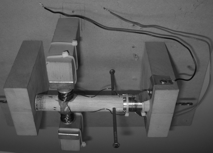
图 4.31 自制电机。#
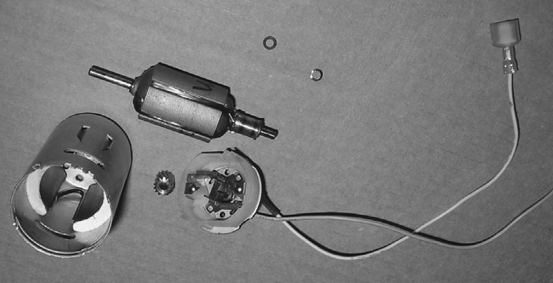
图 4.32 自制电机。#
你可以通过将电线绕成圈缠绕在电枢上来制造电机。电线的两端终止在电刷摩擦的分段上,如 Figure 4.32 所示。
永磁体被安装在机壳内,包围电枢。电枢通过轴承或衬套支撑在机壳中,使其能够自由旋转。在最基本的层面上,电枢上的线圈不过是一个电感器。正如我们之前学习的,电感器通电时会产生磁场。这个磁场类似于永磁体周围的磁场。通过控制电枢周围磁场的开启与关闭,线圈产生的磁场会对永磁体的磁场产生推拉作用。对电枢的电流被按顺序开关(即开启或关闭磁场),使电枢旋转。这被称为*换向*。在直流永磁有刷电机中,电刷就是换向方式。电刷随着电枢转动切换电流通过电枢的不同部分。
直流永磁电机有两个输入和两个输出。你输入电压和电流,输出速度和转矩。一个优点是速度与电压成正比,转矩与电流成正比。电机的电学元件的物理等价物不仅性质相似,而且性能也相互关联。这样想:电压和电流一起等于功率,速度和转矩也一起等于功率。所以在电机中,你输入电功率,输出机械功率。这实际上很合理,不是吗?等效电路如 Figure 4.33 所示。
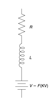
图 4.33 自制电机。#
你觉得电路中的电阻起什么作用?你是否注意过电机工作时发热?这发热来自电机的电阻成分。除了超导体以外,任何电线都有电阻。电枢由导线构成,也有电阻。电流流经电阻时会产生电压降,电阻上的功率转化为热量。欧姆定律依然适用。
电感器产生转动电枢的磁场。电池代表所谓的反电动势,或称*电动势*。如果你用电压表连接电机轴,手动转动轴,会看到一个与转速成正比的电压。在加电压驱动电机时,轴以相同比例的速度旋转。然而,并非施加在端子的所有电压都会到达电机内部,有些会在电阻上损耗。所有这些导致了这种类型电机的一些特征方程。
电压与转速之间的关系称为*电压常数*,单位是伏特每千转每分钟(volts per Krpm),表示为 \(K_e\) 或 \(K_v\):
其中:
- V:
= 端子施加的电压
- I:
= 流过电机的电流
- R:
= 电机的等效电阻 [23]
- Krpm:
= 轴每分钟转速的千转数
方程中的IR项反映了电机中的热损耗。当电流接近零时,这一效应消失。这就是我们之前用电压表测量转动电压时的情况。你看到了吗?这减少了误差,给出了准确的电压常数。
电流与转矩的关系称为转矩常数,通常用Ki表示,单位是英寸盎司每安培(in-oz/amp):
其中:
- T:
= 转矩(英寸盎司)
- I:
= 电流(安培)
这两个常数是相互关联的;改变一个会改变另一个。实际上,如果知道其中一个,可以用以下方程计算另一个:
正如你所见,我们实际上只涉及一个电机常数。这个常数由电枢的绕组数和磁铁的强度控制。绕组越多,电压/转矩常数越大;绕组越少,常数越小。电枢大小和磁铁强度也会影响该常数。
我们现在知道电机的主要电气元件是电阻、电感和电压源。你能推断出机械特性吗?它们是摩擦和惯性。[24] 你首先要注意的是负载或连接到电机轴的物体,很可能是这两个特性的最大贡献者,掩盖了电枢惯性和电刷或轴承摩擦的影响。
惯性会使电机需要时间加速至所需转速,加速时负载和电流增加。达到速度后,惯性会保持电机旋转,因此减速时你会注意到电机所需电流减少。
摩擦会对电机产生恒定负载,在我们的“火花世界”中表现为电流增加。想进一步了解电机相关知识,我推荐读者参考“粉色书”。[25]
My eldest son was elated when he got a Lego Mindstorms kit for Christmas when he was about 8 years old. For those who don’t know, this is a ready-made robot kit based on—you guessed it—Legos. My wife claims I was much more excited than our son was. I beg to differ, but we won’t go into that now. The whole point of a robot is that it moves (a fact that my son wanted to exploit to make a robot to clean his room). The Lego kit uses little DC permanent magnet motors with gears and such to get along. Since this type of motor is so popular, a little discussion about DC permanent magnet motors and how to control them seems prudent.
The DC permanent magnet (PM) brush motor is probably the easiest motor to understand. It consists of just a few parts: an armature, some magnets, a case, wires, and brushes. I remember as a kid making a motor out of a couple of nails, a dowel, and some wire. It looked something like what’s in Figure 4.31.
FIGURE 4.31 A home-built motor.#
FIGURE 4.32 A home-built motor.#
You can make a motor by winding the wire onto the armature in a loop. The ends of the wire terminate on segments that the brushes rub on, as shown in Figure 4.32.
Permanent magnets are attached to the case in such a way as to surround the armature. The armature is supported in the case by bearings or bushings so that it can rotate freely. At its most basic, the coil of wire on the armature is nothing more than an inductor. As we learned earlier, an inductor develops a magnetic field when you pass current through it. This magnetic field is just like the one present around the permanent magnet. By controlling when the magnetic field is present around the armature, you cause the field around the wires to push or pull against the field around the magnet. The current to the armature is switched on and off (which turns the magnetic field on and off) in a sequence that causes the armature to turn. This is called commutation. In the DC PM brush motor, the brushes are the method of commutation. They switch the current through various sections of the armature as it turns.
A DC PM motor has two inputs and two outputs. You put voltage and current in and get speed and torque out. One nice thing is that the speed is proportional to the voltage and the torque is proportional to the current. Motors are devices in which the physical equivalents of electric components are not only similar in nature but are actually linked in performance. Think of it this way: Voltage and current together equal power. Speed and torque together also equal power. So, in a motor, you put electrical power in and get mechanical power out. That actually makes sense, doesn’t it? The equivalent circuit looks like the one shown in Figure 4.33.
FIGURE 4.33 A home-built motor.#
What do you think the resistor is doing in this circuit? Have you ever noticed a motor getting warm when it operates? This heating comes from the resistive component in the motor. Any wire short of a superconductor has resistance. The armature, being made out of wire, also has resistance. Current flowing through a resistor will create a voltage drop across said resistor, and power across that resistor turns into heat. Ohm’s Law still works.
The inductor creates the magnetic field that turns the armature. The battery represents what is called the back EMF, or electromotive force. If you were to spin the shaft of the motor with nothing but a voltmeter hooked up to it, you would see a voltage appear on this meter that is proportional to the speed at which you spin the shaft. When you apply a voltage to the motor, the shaft will spin at a speed in the same proportion. However, not all the voltage you apply to the leads makes it to this point in the motor. Some of it is lost across the resistor. All this leads to some characteristic equations of this type of motor.
The relationship between voltage and speed is known as the voltage constant, with units of volts per Krpm. It is referred to as \(K_e\) or \(K_v\) :
- V:
= the amount of voltage applied at the leads
- I:
= the current flowing through the motor
- R:
= the equivalent resistance of the motor [23]
- Krpm:
= the speed of the shaft in thousands of revolutions per minute
The IR term in this equation accounts for the loss of heat in the motor. As cur- rent approaches zero, this effect disappears. This is what happened earlier when we hooked it up to a voltmeter and spun the shaft, reading the voltage gener- ated. Do you see how that minimizes the error, giving you an accurate idea of the voltage constant?
The relationship between current and torque is known as the torque constant, usually referred to as Ki, which has the units inch-ounces per amp (in-oz/amp):
- T:
= torque in inch-ounces
- I:
= the current in amps
These two constants are linked; changing one changes the other. In fact, if you know one, you can calculate the other with these equations:
As you can see, it turns out that we are really only dealing with one constant in the motor. This constant is controlled by the number of windings on the armature and the strength of the magnets. More windings increase the voltage/torque constant, fewer decrease it. The size of the armature and the strength of the magnets also affect this constant.
We now know that the main electrical components of a motor are resistance, inductance, and a voltage source. Can you extrapolate the mechanical properties? They are friction and inertia. [24] The first thing you should note is that the load, or whatever is hooked to the motor shaft, will likely be the largest contributor to these two characteristic factors, masking the effects of the armature inertia and brush or bearing friction.
Inertia will tend to make the motor take time spinning up to speed, increasing the load and current draw as you accelerate. Once at speed, inertia will tend to keep the motor spinning, so during deceleration you will notice a lessening of the current the motor needs.
Friction will create a constant load on the motor that will appear as an increase in current in our“sparky” universe. To gain further light and knowledge on all things motor, I refer the reader to the“pink book.” [25]
直流电机控制#
DC MOTOR CONTROL
鉴于我们刚刚了解的这种电机类型,我希望很明显,如果我们想控制直流永磁电机的速度,就应该控制其电压。如果想控制转矩,就应该控制电流。如果这还不明白,请再看看直流电机的方程式。
Given what we just learned about this type of motor, I hope it is apparent that if we want to control the speed of a DC permanent magnet motor, we should control the voltage to it. If we want to control the torque, we should control the current. If this doesn’t make sense, take a look at the DC motor equations once more.
速度控制#
SPEED CONTROL
让我们从一个简单的应用开始。假设你想让电机以500转每分钟(rpm)的速度旋转。该电机的Kv为10 V/Krpm。将其代入刚学的方程,你会发现要让电机达到期望速度,大约需要5伏电压(暂且不考虑负载)。那么如何给电机提供5伏呢?有两种方法:线性方法或开关方法。在这两种情况下,你都会从高于电机所需的电压开始,然后降低并施加到电机端子。我们应当了解这两种系统,理解各自的优缺点。
Let’s start with a simple application. Say you want to spin a motor at 500 rpm. This motor has a Kv of 10 V/Krpm. Plug that into the equations we just learned and you find out you need about 5 V to get this motor going at the speed you want (neglecting load for a moment). But how do you go about getting 5 V to the motor? There are two different ways to approach this problem: You can use a linear methodology or a switching methodology. In both cases, you will start with a higher voltage than you want at the motor and then lower it and apply it to the motor leads. We should go over both types of systems to understand the pros and cons of each.
线性控制#
LINEAR CONTROL
最简单的线性控制方法基于电压分压规则。在电源和电机之间串联一个电阻,通过调整电阻值使电机两端获得所需电压——见 Figure 4.34。
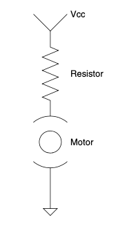
图 4.34 串联电阻的电机。#
此设计最大缺点是电机负载是动态的。随着电机负载变化,流经电机的电流变化,依据欧姆定律,电阻上的电压降变化,进而电机两端的电压发生变化,电机速度必然改变。
然而,如果负载稳定或对变化不敏感,你可以调节此设计使其正常工作。需要注意的是,电阻会因电流和电压产生热量。例如,若Vcc为10 V,电阻值调节使电机两端电压为5 V,则电阻两端电压也是5 V。若电机电流为1 A,则电阻需承受5瓦功率。(实际上,任何合格工程师都不会让电阻长期以最大功率运行,都会适当裕量。)
在此线性控制设计中,电阻可被场效应管、晶体管或其他线性工作模式的放大器替代,从而按需调节电机电压。通过之前学过的反馈方法,也能补偿负载变化,维持输出电压稳定。参见 Figure 4.35。
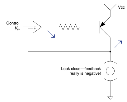
图 4.35 运算放大器控制的电机。#
此设计相较于前者的显著优势是,无论负载变化如何,均能保持电机电压在期望水平,因而速度更稳定,但仍有改进空间,后文将详述。
此类设计的最大缺点与电阻法相同:多余功率转化为热量。唯一优点是,关于电磁干扰(EMI),该设计较为安静。
The simplest way to make a linear control is based on the voltage divider rule. Put a resistor between the power supply and the motor and adjust the resistor’s value until you have the amount of voltage you want across the motor—see Figure 4.34.
FIGURE 4.34 A motor with a resistor in series.#
The biggest drawback to this design is that the motor can be a dynamic load. As the load on the motor changes, the amount of current through the motor changes, which, following Ohm’s Law, changes the voltage drop across the resistor, which changes the voltage across the motor and hence the speed of the motor is destined to change.
However, if the load is consistent or if variability is okay, you can dial this design in and make it work fine. You should note that the resistor will heat up based on the current through it and the voltage across it. For example, if Vcc is 10 V and you set the resistor value such that 5 V is across the motor, this means that there is 5 V across the resistor. If the current drawn by the motor in this case is 1 A, you will need a 5 W resistor to handle the power. (Actually, any engineer worth his salt will not run the power resistor at its maximum wattage but will overrate it liberally.)
In this linear control design, the resistor can be replaced by an FET or transistor or some other type of amplifier operating in linear mode, allowing the voltage to the motor to be adjusted as desired. By using feedback methods as previously learned, the variation in load can also be compensated for so that you can maintain the desired voltage to the output. Take a look at Figure 4.35.
FIGURE 4.35 Op-amp-controlled motor.#
This design has the significant advantage over the previous one of maintaining the voltage to the motor at a desired level, regardless of the changes in load. This will maintain a more constant speed than the previous design, but there is still room for improvement, as we will see later.
The biggest drawback to this type of design is the same as the resistor. Excess power is turned into heat. One benefit, though, is that as far as EMI is con- cerned, it is a quiet design.
开关控制#
SWITCHING CONTROL
与线性控制相反,电机也可以通过开关电源的通断来控制。开关电机控制与开关电源有许多相似之处。许多开关电源设计中都会有一个电感器,在开关闭合时储能,开关断开时释放能量给负载。开关电机控制也类似,不过电感器位于电机内部。开关电源中有一个二极管,将电感器电流导向负载。设计合理的开关电机控制中,也会有执行相同功能的二极管,如 Figure 4.36 所示。
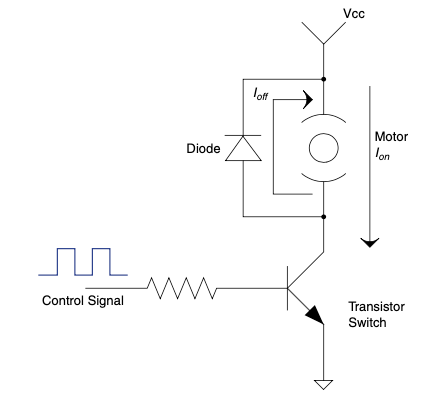
图 4.36 带电机和二极管的晶体管电路。#
开关闭合时,电流流经电机。开关断开时,电感器的电流通过续流二极管回路流经电机。由于电流被回收并供给负载,开关电机控制比线性控制更高效。
需注意的重要事项:此类控制的开关频率必须足够快,才能使电机内的电感器按此方式工作。如果开关未能在电感电流放尽前重新闭合,会感受到电机转矩变化(表现为振动)。
电感器在某种程度上滤波高频开关电源,减少转矩波动和振动。此控制最常见形式称为PWM(脉宽调制)。通过调节PWM占空比,可改变电机功率。
如今开关电机控制非常普遍,主要因其效率高及高功率高频开关器件的广泛应用。
In contrast to linear control, a motor can also be controlled by switching power on and off to the motor. The similarities of switching motor control to switching power supplies are many. In many switching supply designs you will find an inductor that stores the energy when the switch is on and discharges it to the load when the switch is off. The same thing can happen in a switching motor control. The inductor, however, is inside the motor. In the switching supply you will find a diode that directs the current from this inductor to the load. In a correctly designed switching motor control, you will find a diode that performs exactly this function, as shown in Figure 4.36.
FIGURE 4.36 Transistor with motor and diode.#
When the switch is closed, current flows through the motor. When the switch opens, the current from the inductor goes through the freewheel diode back around through the motor. Since this current is recaptured and applied to the load, switching motor controls are more efficient than their linear counterparts.
Some important things to note: The switching frequency of this type of control needs to be fast enough for the inductor in the motor to act this way. If the switch doesn’t turn back on before all the current has discharged from the inductor, you will feel the torque change in the motor (it will manifest itself as a vibration).
In a way, the inductor filters the high frequency of the switching power, reducing torque ripple and thus vibration. The most common form of control in this case is called PWM for pulse width modulation. By varying the duty cycle of the PWM, the amount of power to the motor is varied.
Switching motor controls are very prevalent these days. This is primarily due to their efficiency and the proliferation of high-power, high-frequency switching devices.
保持速度#
MAINTAINING SPEED
通常会使用某种电压反馈来将控制输出电压维持在期望水平。记住,在直流永磁电机中,输出轴的速度与施加的电压成正比。这使得速度维持变得简单。然而,如果你翻回几页,会注意到方程中的IR项代表了所谓的损耗。这些损耗作为热量在线圈电阻(以及刷子中)上消耗掉。损耗与电机中的电流(I)成正比,而电流与电机轴上的负载成正比。
这意味着随着电机负载的变化,损耗也会变化,导致速度发生变化。可以这样理解:作为热量消耗掉的电压永远不会用于驱动电机轴旋转——见 Figure 4.37。
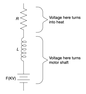
图 4.37 电机内部发生了什么?#
有两种方式来补偿这一点。一种是使用速度反馈,调整电机的输出电压以维持恒定速度。另一种是直接补偿损耗本身。
在大多数直流电机控制设计中,你会发现一个电压反馈环路完成了90%的速度控制工作。除此之外,还会有一个速度反馈控制环路补偿剩余的变化——见 Figure 4.38。
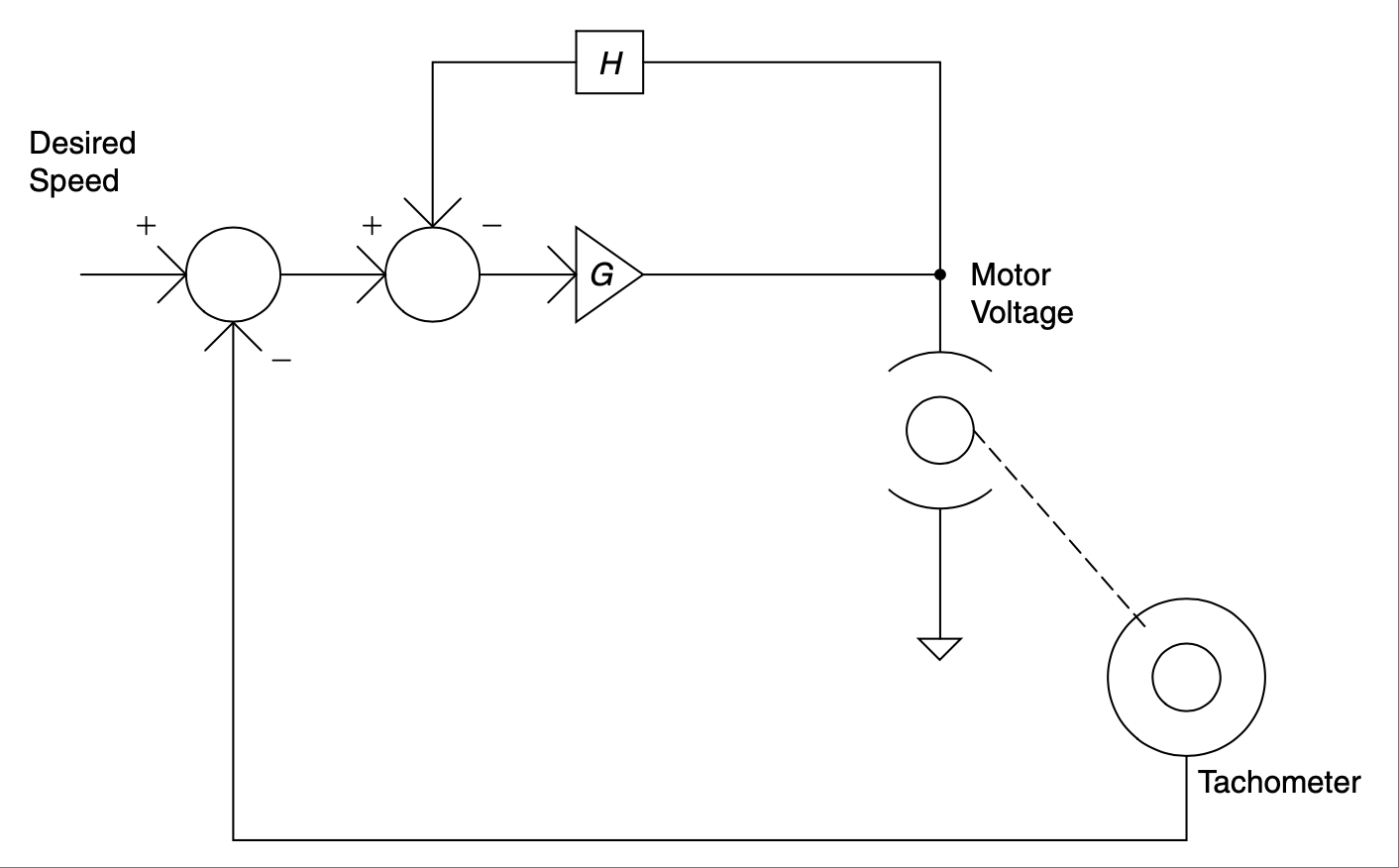
图 4.38 速度反馈的框图。#
虽然反馈你想控制的信号通常是好主意,但有时你可能没有这个条件,或者有理由不使用速度反馈。如果是这样,你可以使用另一种速度控制近似方法,称为IR 补偿——见 Figure 4.39。这种方法通过检测电机电流来监测电机负载。由于热损耗与电流成正比。如果你知道电机的电阻,就能计算出多少电压变成了热量,没有传递到输出轴。将这部分电压加到电机输入端,就能得到相当不错的速度控制近似,且不需要转速表!
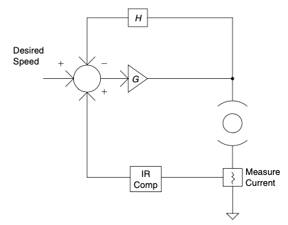
图 4.39 IR补偿反馈框图。#
总之,控制直流永磁电机速度是最简单的运动控制问题之一,但这“简单”是相对于其它方案而言的,仍然是一个不小的“学习量”。因此,如果你想学习运动控制,我建议先从这里开始,再逐步学习其它类型电机。
Often some sort of voltage feedback is used to maintain the output voltage of the control to a desired level. Remember that in the DC PM motor the speed of the output shaft is proportional to the voltage applied. That makes it nice for main- taining speed. However, if you flip back a few pages you will notice the IR com- ponent of that equation represents what are known as losses. These losses are burned up as heat across the resistance of the wire in the motor armature (plus a little in the brushes). The loss is proportional to the current (I) through the motor, and the current is proportional to the load on the motor shaft.
This means that as load varies on the motor, the amount of loss varies. This results in a change of speed. Think of it like this: The voltage that gets burned up as heat never makes it to spinning the motor shaft—see Figure 4.37.
FIGURE 4.37 What happens inside the motor?#
There are two ways to compensate for this. One way is to use speed feedback to adjust the voltage output to the motor to maintain a constant speed. The other is to compensate for the losses themselves.
In most DC motor control designs, you will find a voltage feedback loop that does 90% of the speed control work. Then, external to that, you will find a speed feedback control loop that will compensate for the rest of the variation—see Figure 4.38.
FIGURE 4.38 Block diagram of speed feedback.#
Though it is generally a good idea to feed back the signal you want to control, there could be times you do not have that luxury, or maybe there are reasons you do not want to use speed feedback. If this is the case, you can use another speed control approximation called IR compensation—see Figure 4.39. This is a method in which you monitor the load on the motor by sensing the current through the motor. The loss due to heat is proportional to this current. If you know the resistance of the motor, you can calculate how much voltage turns into heat, never making it to the output shaft. Add this much voltage to the input to the motor and you have a fairly good approximate speed control and you didn’t need a tachometer!
FIGURE 4.39 Block diagram of IR comp feedback.#
All in all, controlling a DC PM motor speed is one of the simplest motion- control problems to tackle, but it is simple only relative to the other options out there. It is still a significant“chunk o’ learnin’” to swallow. For this reason I suggest starting here if you want to learn motion control before moving on to some of the other available motors.
转矩控制#
Torque Control
当你使电机转子停止转动时,电流会急剧增大。根据电机和设计不同,这可能超过控制器能承受的电流。在这种情况下,你可能需要一个限流电路。
该电路监测电机电流,并在预设值时减少输出,限制电机可用电流。
在直流永磁电机中,控制电流即是控制转矩。不信?翻回几页看看转矩常数方程,单位是英寸盎司/安培。这是线性关系——电流越大,输出轴转矩越大。
这意味着,当连接到电机时,恒流电源会产生恒定转矩。当控制达到电流限制时,控制器从恒压源转变为恒流源,以保护电机和控制器免受损坏。
One thing that happens when you take a motor and stop the rotor is a huge increase in current. Depending on the motor and your design, this could be more current than your control can handle. In this case you might need a current-limiting circuit.
This is a circuit that monitors the current used by the motor and, at a preset level, scales back the output, limiting the current available to the motor.
In a DC PM motor, when you control the current, you control the torque. Don’t believe me? Flip back a few pages and look at the torque constant equations. The units are in-oz per amp. This is a linear relationship—the more current through the motor, the more torque at the output shaft.
What all this means is that a constant current supply will create a constant torque when hooked up to a motor. This is essentially what happens when a control hits its current limit. The control goes from being a constant voltage supply to a constant current supply. This protects the motor and the control from damage.
制动#
Braking
想象你骑着电动滑板车飞驰下坡。“哇,”你想到,“如果能利用我浪费的能量来减速该多好啊。应该有办法给电池充电。嘿,我是工程师,”你对自己说,“何不设计一个再生制动?”我也曾有过这样的想法,并且一直能很好地忽略它[26]_。
前不久有人让我设计带有再生制动电路的电机控制。虽然做过多个控制器,但没有带再生制动的,我先上网查阅资料。我不盲目“勇往直前”,即如果别人已经走过这条路,我当然想知道他们怎么走的。知道路径尽头后,我才敢进入未知。
然而,这次几个小时的搜索基本无果。我只需要一个简洁的解释和可能的电路图(尤其是针对直流永磁电机),但网上多是长篇大论解释它做什么,少有具体实现方法。最终,我没找到简单解释,可能在某处有,但弹窗太多让我厌烦了。
正如你可能猜到的,我认为这缺乏说明是对我的个人挑战,我必须纠正。以下是我整理的内容,经过我自身智力(管理职位越久,智力似乎越低)萃取,呈现给读者,力求易懂。在看过“比生面包还棒的最佳创意”和本田Insight再生制动的精彩介绍后,以下内容应运而生。
Imagine careening down a hill on your electric scooter.“Gosh,” you think to yourself,“it would be nice to use some of the energy I’m wasting to slow this vehicle down. There ought to be a way to make it recharge the batteries. Hey, I’m an engineer,” you say to yourself,“Why don’t I design a regenerative brake?” Just such a thought has come into my head and I have been able to ignore [26] it quite effectively until now.
Some time ago I was asked to design a motor control with a regenerative braking circuit. Having done several controls, but none with regenerative braking, I started by perusing the Internet. I don’t follow Star Trek’s creed to boldly go where no man has gone before on a whim. That is to say, if someone has been there already, I would sure like to know the path he or she took. Once the end of that path has been found, I will then venture into the unknown.
Anyway, in this case, several hours of searching were somewhat futile. A simple and concise explanation and possibly a schematic (particularly for a PM DC motor) were all I needed. There were reams [27] of information explaining what it does but not much was there showing exactly how it was done. Alas, my effort to find the simple explanation was to no avail. Maybe it was out there somewhere, but I got sick of all the pop-ups.
As you might have guessed by now, I take such a lack as a personal affront that I must correct. The following is what I have pieced together in my own mind, distilled down to my level of intelligence (the longer I spend in management, the lower this level seems to be), then ousted to my readers in a form I hope is easy to understand. After I looked at the best idea since raw toast and the nice read about the Honda Insight’s regenerative brake, the following is what came out.
不再有秘密!#
No More Secrets!
我发现有地方称再生制动是电机控制的“保守秘密”。但我认为真相只是解释得不好。让我们从 Figure 4.40 开始,这是一个简单的直流永磁电机PWM控制器示意图。
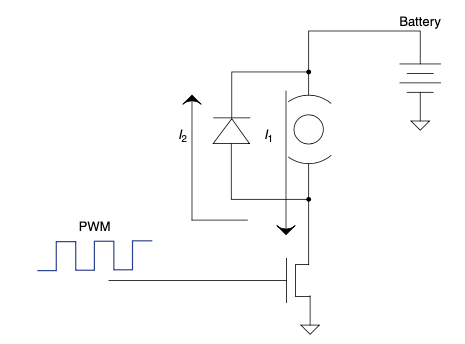
图 4.40 PWM电机控制。#
PWM信号输入开关,如MOSFET,频率足够高以保持电机内电感电流连续,类似开关电源。当PWM关闭时,电流通过二极管(有时称为续流二极管)流动。我理解这部分,但一直疑惑的是,如何让一个以低于电池输出电压转速旋转的电机将电流推回电池?
让我们先对之前电路做个小改动,如 Figure 4.41 所示。将二极管换成同步开关,当主开关闭合时该开关断开,反之亦然。此讨论中暂不考虑高侧和低侧FET驱动方式的特殊要求。
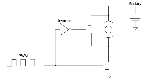
图 4.41 用FET替代二极管的PWM电机控制。#
我多次读过这种拓扑结构。通常被提及是为了提高控制器的热效率,因为FET的压降远低于二极管。我之前没想到它还能作为再生制动,直到自己弄懂它的工作原理。以下是其工作方式。
One place I found said that regenerative braking is the well-kept secret of motor control. However, when I learned the truth, I think it is just poorly explained. Let’s start with Figure 4.40, a diagram of a simple PWM controller for a DC PM motor.
FIGURE 4.40 PWM motor control.#
A PWM is fed into a switch, such as a MOSFET, at a frequency that is high enough to keep current flowing in the inductor inside the motor, not at all unlike a switching power supply. When the PWM shuts off, the current flows through the diode (sometimes referred to as a freewheeler diode). That part I could understand, but the question that I kept asking myself was how do you get a motor, which is spinning at a lower voltage than the output of the battery, to push current back into the battery?
Let’s start with a small change to our earlier circuit, as shown in Figure 4.41. We will replace the diode with a synchronous switch that goes off when the primary goes on, and vice versa. For the purpose of this discussion we will ignore the fact that the FETs need particular driving methodologies for the high side and the low side of a motor.
FIGURE 4.41 PWM motor control with FET in place of diode.#
I had read about this topology many times. It is usually brought up as a way to make your controller more efficient in terms of heat loss. This is because the FET has a significantly lower voltage drop across it than the diode does. I had no idea that it also functions as a regenerative brake, until I figured it out for myself. Here is how it works.
稍作阐述#
A Little Elaboration
请记住,在这个控制器的原始版本中,电机两端的电压取决于PWM的占空比,但它是相对于电池的正极参考的,而不是负极。这帮助我保持了对其的正确认识。
假设我们有一个12 V直流电池,电机两端电压为6 V。这意味着你会看到电机底部到地的平均电压为6 V。现在假设你让电机转速超过了6 V所对应的速度,例如7 V。如果你保持电机底部的平均电压不变,你将有额外1 V可以回馈到电池中。这个解释不完全准确,但我认为能让你进入正确的思考状态。如果你追究这个结论,会认为前面带二极管的版本也应该有再生功能,但事实并非如此。
让我详细说明。带二极管版本时,不会产生制动力。制动力是在二极管被FET替代时产生的。当续流FET导通时,电机产生的电压被短路回自身。这提供了制动力,并使电机中产生反方向电流。记住电感器的规则(因为电机中有相当大的电感)。一旦电流开始流动,它不喜欢停止。所以当高侧开关断开,低侧开关闭合时,电流被推入电池。魔法棒一挥,瞧,你得到了再生!
Keep in mind that in the original version of this controller there is a voltage across the motor that depends on the duty cycle of the PWM, but it is refer- enced to the positive output of the battery, not the negative side. That helped me to keep it in perspective.
Assume that we have a 12 V DC battery and there is 6 V DC across the motor. That means you would see an average of 6 V DC from the bottom of the motor to ground. Now let’s say that you spin the motor faster than 6 V—for example, 7 V. If you keep the same average voltage at the bottom of the motor, you will have 1 V extra to dump into the battery. This explanation doesn’t entirely jive, but I think it will get you in the right frame of thinking. If you follow it to its conclusion, you will think that the previous version with the diode should also regenerate, but it does not.
Let me elaborate. With the diode version, there is no braking force generated. That comes into play when the diode is replaced by the FET. When the free- wheel FET turns on, the voltage generated by the motor is shorted back into itself. This provides the braking force and a current flow in the opposite direc- tion through the motor. Remember the rule of inductors (since there is a decent-sized inductor in the motor). Once a current is flowing, it doesn’t like to stop. So when the high side opens and the low side closes, current is pushed into the battery. Wave of the wand and voilà, you have regeneration!
再生其实没那么难#
Regeneration Ain’t So Bad
事实证明,再生一点也不难。实际上,如果你这样看,再生几乎是让控制器更高效的附带好处。现在如果有办法让效率超过100%,嗯……
It turns out that regeneration isn’t so tough at all. In fact, it is almost a side benefit of making your controller more efficient, if you want to look at it that way. Now if there were just some way of making it more than 100% efficient, hmm … .
改变方向#
Changing Directions
在直流永磁电机中,改变转子转向相当简单。你只需反转电机端子的电压即可。常用的方法称为H桥,因其绘制在纸上的形状而得名,见 Figure 4.42。
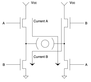
图 4.42 H桥电机控制。#
如前所述,H桥既可以是线性设计,也可以是开关模式设计。理论相同,但更复杂。例如,你不能同时打开桥臂同一侧的两个开关,否则会导致电源短路。这被称为直通(shoot through),通常会产生大量的“魔法烟雾”。[28]
通过同步切换对侧高低端的开关(如FET),就能产生前面提到的制动/再生效果。电压和电流反馈变得更复杂,因为电机的一侧不再总是接地或固定电位。你需要一些能处理大电压摆幅的差分放大器来保证系统正常工作。
In a DC PM motor, it is fairly easy to change the direction of spin of the arma- ture. You simply need to reverse the voltage to the motor leads. A common way to do this is known as an H bridge, so called for the way it looks when drawn on a piece of paper, as shown in Figure 4.42.
FIGURE 4.42 H bridge motor control.#
As previously discussed, the H bridge can be a linear or switch mode design. The same theory is applicable, but it does become more complex. For example, you don’t want to turn on both legs on one side of the bridge because you will create a short across your power supply. This is known as shoot through and will usually cause copious emissions of magic smoke. [28]
Synchronous switching of the opposing high and low legs with the appropriate devices (like FETs) will create the braking/regenerative effect that we have already mentioned. Voltage and current feedback become more complex due to the fact that one leg of the motor is no longer tied to one spot all the time. You will need some differential amplifiers that can handle some large voltage swings to get things working right.
让东西动起来的结论#
Making Stuff Move Conclusion
控制电机是电气工程中最复杂且最有成就感的事情之一。挫折和失败最终会被看到物体运动的自豪感所回报!我不可能在这本书中涵盖电机控制的所有方面。但我希望我已经提供了足够的基础理解,使你在面对电机并做更多研究时,能够理解你所遇到的信息。
Controlling motors is one of the most complex and rewarding things you will do in electrical engineering. Setback and frustration will be rewarded with the pride of seeing something move! There is no way I can possibly cover all aspects of motor control in this text. I do hope, however, that I have given you enough basic understanding that when you tackle motors and do more research on the topic, you will be able to understand what you find out there.
其他类型电机#
SOME OTHER TYPES OF MOTORS
你会遇到许多种类的电机。人们玩弄不同电机制造方式的历史几乎和用电一样久远。下面是一些各种类型直流电机的概述。
You will run into many types of motors. People have been goofing around with different ways to make a motor nearly as long as they have been messing with electricity. Here is a bit of overview on some various types of DC motors.
无刷直流电机#
Brushless DC Motors
无刷直流电机,如 Figure 4.43 所示,是我们之前讨论的直流永磁电机的近亲,但它们通常不使用刷子换向,而是采用某种电子控制。为此,电机内部通常装有永磁体(相当于直流永磁电机中的转子),称为转子。绕组位于外部,通常称为定子或场绕组。[29] 不一定非要磁铁在内侧、绕组在外侧,但绕组是固定不动的,磁铁旋转。通过按顺序开关定子绕组,产生作用于转子的转矩。这称为电子换向,而非我们之前学习过的机械刷换向。
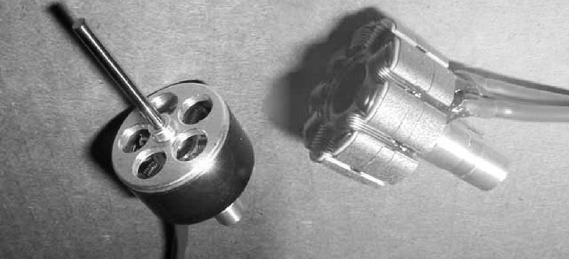
图 4.43 我的遥控飞机上的酷炫无刷直流电机。#
你经常会听说无刷直流电机比直流永磁有刷电机效率高很多。这其中有些夸大。虽然这种说法有时成立,但并非完全因为无刷。效率数字的提升主要来自磁铁的选择。大多数无刷电机使用稀土磁铁,其磁通密度远高于普通陶瓷磁铁。这意味着为了达到相同转矩和转速,绕组的圈数更少。圈数减少意味着线材更短,电阻更低。绕组电阻是电机损耗的最大来源,因此减少电阻使电机更高效。
直流永磁电机通常用陶瓷磁铁,导致绕组圈数多。为了提高效率,需要增大线径以降低电阻。直流有刷电机也能使用强磁铁。我最常见的是爱好商店里的遥控飞机电机。装配了这种“超级”磁铁的直流永磁电机效率相当接近无刷电机。
假设轴承良好,电机的下一个损耗点是换向。直流永磁电机中,刷子和刷子接触面是换向方式。这个接口不完美,会产生电阻损耗。无刷直流电机则用某种硅开关(如FET)完成换向。通常至少需要六个此类器件进行换向。这些FET有电阻成分(称为RDS on),以热量形式损耗能量。
无刷电机最大优势就是无刷。直流永磁电机中的刷子几乎总是最先磨损的部件。刷子天生是消耗品,但这不妨碍它们广泛使用。很多应用中刷子电机表现良好。
需要注意的是,无刷电机的控制器更复杂,需要3到6倍于有刷电机的功率器件。但一旦你掌握了它们,几乎完成了让电机双向运转的大部分投资。所以如果需要双向控制,无刷电机可能更合适。
The brushless DC motors shown in Figure 4.43 are cousins to the DC PM motor we discussed earlier, but instead of using brushes for commutation, they usually use some type of electronic control. To accomplish this, usually the inside of the motor has the permanent magnets (where the armature is in the DC PM motor). This is known as the rotor. The windings are on the outside and are usually referred to as the stator, or field windings. [29] There is no require- ment for the magnets to be on the inside and the windings on the outside, but the windings are stationary and the magnets rotate. The rotor is turned by switching the stator windings on and off in a sequence that creates torque on the rotor. This is known as electronic commutation, as opposed to brush commu- tation, which we already learned about.
FIGURE 4.43 Cool little brushless DC motor out of my RC airplane.#
Often you will be told how a DC brushless motor is so much more efficient than a DC PM brush motor. There is some hype to dig through here. Though this claim can be true, it is not entirely due to the fact that it is a brushless motor, as the brushless motor guys would have you believe. You will see numbers showing improved efficiency, but that is generally due to the choice of magnets. Most brushless motors are using rare Earth magnets that have a much higher flux density than the more common ceramic kind. What this results in is fewer turns of wire for the same torque and speed. Fewer turns of wire means shorter wire, which means lower resistance. Since the resistance of the windings is the largest loss in the motor, this makes the motor more efficient.
DC PM motors commonly use the ceramic magnets, resulting in more turns of wire. To make them more efficient, you need to increase the wire diameter to lower its resistance. It is possible to use the stronger magnets in a DC brush motor. The most common place I have seen this is in hobby stores. There are some pretty cool motors like this for RC airplanes. When built with these “super” magnets, the DC PM motor is pretty close to the same efficiency as the DC brushless motor.
Assuming good bearings, the next point of loss in a motor is in commutation. In the DC PM motor the brushes and brush contacts are the method of commu- tation. This interface is not perfect and creates a resistive loss. In the DC brush- less motor, commutation is done with some type of silicon switch such as an FET, for example. Typically, it takes at least six of these parts to commutate a DC brushless motor. These FETs have a resistive component (called RDS on) that causes loss in the form of heat.
The biggest advantage to a brushless motor is right there in its name. It has no brushes. The brush in the DC PM motor will nearly always be the first thing to wear out. Brushes by their nature are designed to wear out, but don’t let that stop you. There are many types of brush motors available, and often they will be just fine for the application.
One thing to note about brushless motors is that the controllers are more com- plex, requiring three to six times the power devices that brush motors use. But once you have them under control, you have already spent most of the money needed to make them go in both directions. So if that is a feature needed, it could make a brushless motor more of a candidate.
步进电机#
Stepper Motors
步进电机是一种直流电机,每次给绕组通电时,输出轴都会移动一个特定的距离。它们是无刷电机的近亲,还有一种叫做开关磁阻电机的奇特电机。[30] 这种能够移动特定步距的能力,使得步进电机广泛应用于定位机构。打印机中大量使用它们。
定位相对简单,因为你可以给绕组通电并计算步数,从而确定电机轴的位置。步进电机的特征包括运动转矩和保持转矩。这一点很重要,因为如果超过其中任一转矩,电机可能会打滑,导致计数错误。
Stepper motors are a type of DC motor in which the output moves a specific distance each time you energize a winding. They are a cousin to the brushless motor and a weird animal called the switched reluctance motor. [30] The ability to move a specific step makes these devices commonly used in positioning mechanisms. Printers use them by the bucket load.
Positioning is relatively easy since you can energize the windings and count the number of steps you have made to determine where the motor shaft is. Stepper motors are characterized by their moving torque and holding torque. This is important to know because if you exceed either, your motor could slip, and that would cause your count to be off.
经验法则(Thumb Rules)
在电机中,你输入电功率,输出机械功率。
电压 * 电流 = 功率;速度 * 转矩 = 功率。
线性控制产生的电磁干扰较少。
线性控制简单且成本低。
线性控制因热损失效率较低。
开关控制效率更高。
开关控制产生更多电磁干扰。
开关控制通常更复杂且成本更高。
直流永磁电机中,恒定电压产生恒定速度。
直流永磁电机中,恒定电流产生恒定转矩。
切换电路中不要忘记续流二极管。
用场效应管替代续流二极管即可实现制动。
使用H桥可改变转向。
无刷电机控制本质上是双向的。
步进电机以小步距或增量移动。
In a motor, you put electrical power in and get mechanical power out.
Voltage * current = power; speed * torque = power.
Linear controls cause less EMI.
Linear controls are simple and cheap.
Linear controls are less efficient due to heat loss.
Switching controls are more efficient.
Switching controls cause more EMI.
Switching controls are generally more complex and expensive.
Constant voltage makes for constant speed with a DC PM motor.
Constant current makes for constant torque with a DC PM motor.
Don’t forget the freewheel diode in a switcher.
Replace the freewheel diode with an FET and you have a brake.
Use an H bridge to change directions.
Brushless motor controls are inherently bidirectional.
Stepper motors move in small steps or increments.
交流电机和通用电机#
AC and Universal Motors
如前所述,很久以前,一个名叫特斯拉的聪明人帮助我们所有人说服权威机构,我们应该采用 交流电 作为电力分配方式(相对于爱迪生想要的本地直流发电机)。促成这场辩论的关键因素之一是特斯拉发明了 交流电 电机。
交流电机有很多种类。这里我们将回顾最常见的一种: 交流电 感应电机。
交流感应电机通过改变定子的磁场感应出电枢电流。该感应电流反过来产生一个磁场,促使转子旋转,抵抗第一个磁场。刚学时,我觉得交流电机就像“自我驱动”一样。结果是,电机通常有一个“最佳点”,在此转速下产生最大速度和转矩。低速时转矩快速下降。因此,交流电机以低速转矩不足著称(与我们刚讨论的直流电机不同)。鉴于交流电机运行于正弦交流信号,绝大多数交流电机为固定速度输出,速度取决于交流信号的频率。还有变频驱动或控制,结构类似无刷直流驱动。它们能改变交流电机的频率,实现变速交流驱动。由于交流电机没有简单的转矩-速度曲线,这些控制器较为复杂,常用DSP芯片来计算所需控制算法。
交流电机已存在多年,价格相对低廉,且无刷设计寿命长。它们可以同步构造,如步进电机,因此每个交流周期都能保证转动一定角度。它们广泛应用于各种场合:冰箱压缩机驱动、冰箱制冰电路计时。早在“二极管普及时代”之前,数以百万计的时钟也使用它们。
通用电机类似无永磁体的永磁电机。它们使用外部带电流绕组代替永磁体。之所以称为通用电机,是因为它们既能接交流电源,也能接直流电源。我在旧牛奶棚重接电机线路时,曾多次被自己电击,试图搞懂它们。
各种形状、尺寸、类型和电压规格的电机应有尽有。希望我提供的背景知识能让你在被问及此话题时至少能听起来很专业。
As we mentioned earlier, long ago a smart guy by the name of Tesla helped us all by convincing the powers that be that we should have an AC means of power distribution (vs. the local DC generators that Edison wanted). One key factor that helped with this debate was Tesla’s invention of the AC motor.
There are many types of AC motors. One of the most common and the one we are going to review here is the AC induction motor.
An AC induction motor induces a current in the armature by varying the magnetic field in the stator. This induced current in turn creates a magnetic field that causes the rotor to turn, pushing against the first magnetic field. When I first learned this, it seemed to me that an AC motor can pick itself up by its bootstraps, so to speak. One result is that the motor tends to have a“sweet spot” where the rotational speed is just right, generating maximum speed and torque. At lower speeds the torque drops off pretty fast. This leads to the fact that AC motors are not known for low-speed torque (unlike the DC versions we just discussed). For this reason and the fact that AC motors run off a sinusoidal alternating signal, a huge percentage of AC motors are fixed-speed outputs where the speed depends on the frequency of the AC signal. There are variable frequency drives or controls, similar in architecture to DC brushless drives. They can vary the frequency into an AC motor, creating a variable-speed AC drive. Since AC motors do not have such a simple torque speed curve, these controls can be fairly complex, often using DSP chips to handle all the math needed to get what you want out of one of them.
AC motors have been around for years, making them relatively inexpensive, and their lack of brushes makes them last a long time. They can be built synchronously, like a stepper motor, so that you know they have moved a set distance every cycle of the AC wave. You will see them in all sorts of places: running compressors in a refrigerator to timing the icemaker circuit in the same fridge. Back before the“day of the diode,” they were used in millions of clocks.
Universal motors are like PM motors without the permanent magnet. They use windings with current flowing through them in the outer field instead of said magnets. What makes them universal is the ability to wire them to work with an AC or DC source. I shocked myself more than once rewiring the motor down in the old milking barn trying to figure this out.
Motors of all shapes, sizes, types, and voltage preferences are out there. Hopefully I have provided enough background so you at least sound smart when you’re asked about this topic.
电磁阀#
Solenoids
电磁阀是一种电磁装置,通常只移动到两个位置。类似步进电机,电磁阀以保持力和移动力来评价。
取一根线圈和一根刚好能放入线圈的铁棒,如 Figure 4.44 所示。
通电线圈后,铁棒由于磁通的作用会居中于线圈内。铁棒实际上不愿离开温暖舒适的线圈。铁磁材料自发对齐磁场的现象称为磁阻(reluctance)。
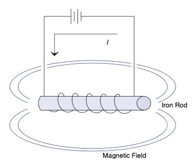
图 4.44 线圈中的铁棒。#
断开磁场后,铁棒可以轻松移动。通常用弹簧将铁棒推离线圈,直到再次通电,铁棒又表现出磁阻作用。
电磁阀非常适合需要短距离直线运动且由电子控制的场合。此外,这一概念是电磁炮的基础。但本书无暇详述。遗憾的是,电磁炮很有趣。
The solenoid is an electromagnetic device that typically moves to only two positions. Akin to the stepper motor, solenoids are rated by holding force and moving force.
Take a coil of wire and an iron rod that just fits inside the coil, as shown in Figure 4.44.
Energize the coil. The rod will center itself in the coil due to the magnetic flux running through it. It is in fact reluctant to leave the warm home of its cozy little coil. This tendency for ferrous material to align itself with magnetic fields is known as reluctance.
FIGURE 4.44 Iron rod in coil of wire.#
Shut the magnetic field down and the rod moves easily. Usually a spring is used to push the rod out of its cozy coil shell until power is switched back on and the rod returns to showing its reluctance yet again.
Solenoids are great if you need a short linear motion that is controlled by something electronic. Also, this concept is the basis for an electromagnetic cannon. We don’t have time to cover that topic in this book, though. Too bad; cannons are fun.
继电器#
Relays
继电器实际上不会让任何东西移动,除了内部用来闭合开关的部分,所以看起来可能有些不合适在此讨论。但它们确实是机电设备,我想不到更合适的地方介绍它们。继电器非常坚固;它们比晶体管还早出现,并且至今仍在使用,这说明了它们的价值。它们基本上是电磁阀和开关的组合。磁力将开关拉闭或拉开,取决于具体设备。继电器上的标记通常显示线圈操作继电器,标签有NO、NC和C。这些缩写在开关中也常见,分别表示常开、常闭和公共端。NO和NC表示线圈未通电时开关状态,C为这两个开关的公共连接。
继电器有两个重要参数:线圈电压和触点额定值。若线圈驱动不足,开关可能闭合但不能保证正常工作。触点通常有最大和最小电流额定值。大多数工程师关注最大电流,但常忽视最小电流。在许多电力应用中(现今很常见),继电器开关断开时需有一定电流通过,该电流产生电弧,清洁触点并防止腐蚀。如果你的继电器用久后失效,很可能是未满足此规格。设计时使用继电器,你会听到满意的“咔哒”声,告诉你魔法盒子中的某个部件正在工作。
Relays don’t actually make anything move except the part inside them that closes a switch, so they might seem a little out of place in this discussion. However, they are definitely electromechanical in nature and I couldn’t think of a better place to talk about them. Relays are very tough; they predate the transistor by a long time and are still in use. That should say something. They are basically the combination of a solenoid and a switch. A magnetic force pulls the switch shut or open, depending on the particular device. Markings on a relay usually indicate the coil that operates the relay and the labels NO, NC, and C. These abbreviations, also sometimes seen on switches, mean normally open, normally closed, and common, respectively. NO and NC refer to the state of the switch when the coil isn’t energized. C is a connection to both these switches.
There are two important specs on a relay: the coil voltage and the contact ratings. If you under-drive the coil, you might get the switch to close, but there are no guarantees. Contacts are often rated at a minimum as well as a maximum current. Most engineers are diligent about paying attention to the max current, but they often ignore the minimum current. Many relays used in a power setting (which is very common these days) rely on a certain amount of current to be pre- sent when the switch opens. This current creates an arc that cleans the contacts and keeps them from corroding. Do you have a relay that simply stops working after a while? Chances are you are not meeting this spec. Use a relay in your design and you get to hear that satisfying click, letting you know that something is really working in that magic box.
捕捉飞虫#
Catching Flies
所有这些电机、电磁阀和继电器的共同点是它们都有一组在线路中切换电流的线圈。线圈本质上是电感器,而电感器不喜欢电流的变化。[31] 那么,当你切断电感中的电流会发生什么呢?当电流被切断时,磁场崩溃,会产生一个很大的电压尖峰(因为它想保持电流继续流动)。这个尖峰有时被称为回扫电压。为了防止这个尖峰损坏元件并利用其能量,大多数应用中会使用一个回扫二极管,也称为续流二极管,将这个尖峰回送到其来源,如 图 4.45 所示。
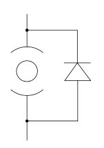
图 4.45 电机周围的回扫二极管示例。#
如果该电路中LR的响应比开关频率慢,二极管会作为滤波器的一部分,使电流继续流过电机。它平滑了电流变化,从而平滑了转矩变化。(记住转矩与电流成正比?)
在其他情况下,这个二极管可能只是捕获瞬态信号以防止电路损坏。图 4.46 展示了使用二极管保护继电器线圈的示例。
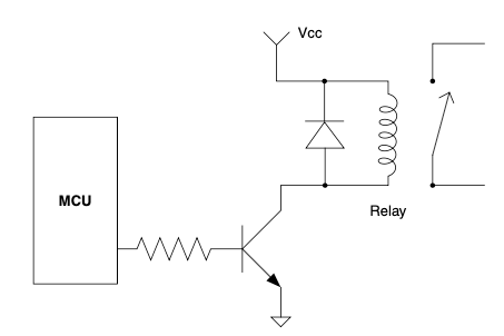
图 4.46 继电器线圈上的回扫二极管。#
你可以看到电压尖峰,也称为感性反冲或反电动势,永远不会超过约0.7 V,因为一旦超过,它就会使二极管正向导通,电流流回电感的另一端。现在你知道如何用二极管制作“捕虫器”了。
让东西动起来真是超级酷。我最近参加了Google IO,听了机器人工具系统的课程。我儿子那套乐高Mindstorms从没用来收拾房间,所以房间仍然乱糟糟的,他倒是开始用旧汤罐制作喷气发动机了,但我刚刚给他发了一个机器人叠衣服的视频!房间清洁机器人指日可待!
One thing all these motors, solenoids, and relays have in common is a coil of wire that is switching current at some point. A coil of wire is an inductor, and an inductor doesn’t like current changes. [31] So what happens when you shut off the current in an inductor? As the magnetic field collapses when you cut off the current, a large voltage spike is generated (because it wants to keep current flowing). This spike is sometimes called the flyback. To keep this spike from damaging components and to use the energy in it, most applications employ a flyback or, as it is also called, a freewheel diode that shunts this spike back to its source, as shown in Figure 4.45.
FIGURE 4.45 An example of a flyback diode around a motor.#
If the response of the LR in this circuit is slower than the switching frequency, the diode acts as part of a filter keeping current moving through the motor. It smoothes out current changes, which in turn smoothes the torque changes. (Remember how torque is proportional to current?)
In other cases, this diode might simply be capturing a transient signal to prevent circuit damage. Figure 4.46 shows an example using a diode to protect a relay circuit.
FIGURE 4.46 Flyback diode on a relay coil.#
You can see that the voltage spike, inductive kick, or back EMF, as it is called, never gets over–0.7 V because once it does, it forward-biases the diode and current flows back into the other end of the inductor. Now you know how to make a fly catcher out of a diode.
Making stuff move is incredibly cool. I recently attended Google IO and had to hit the class on robotic operating systems. My son never did get those Lego mindstorms to clean his room, so it is still a mess and he has moved on to making jet engines out of old soup cans, but I just had to send him a video of a robot folding laundry that I saw there! The room cleaner will soon be a reality!
经验法则(Thumb Rules)
当经验法则太多时,把它们拆分成更易消化的小块。
交流电 感应电机会在铁芯中感应出电流,进而产生转动轴的磁场。
电磁阀在线圈通电时不愿离开舒适的线圈“洞穴”。
注意继电器的最小开关电流。
用二极管捕捉电压尖峰,保护电路,除非你想做个电击盒吓唬朋友。
谁不想要一个机器人帮忙收拾房间呢?
When the thumb rules go on and on, break them into smaller, more digestible pieces.
AC induction motors induce a current in the core, which in turn creates a magnetic field that turns the shaft.
Solenoids are reluctant to leave the cozy coil cave when current is on.
Pay attention to the minimum switching current on relays.
Catch your flies with diodes to keep voltage spikes out of your circuits unless you are trying to make a shock box to surprise your buddy.
Who wouldn’t want a robot to clean their room?