第 5 章 工具#
CHAPTER 5 Tools
使用什么工具?什么时候用?这正是老生常谈的问题。对电气工程师来说,工具数不胜数。本章并不打算对各种工具进行详尽分析,而是为如何选择合适的工具、以及如何正确设置工具以获取所需信息提供一些指导。
What tools to use and when to use them? That is the proverbial question. There are innumerable tools available to the electrical engineer. This chapter is not intended to be an exhaustive analysis of various tools but rather a guideline for selecting the proper tool and for setting it up right to get the information you are looking for.
让无形变得可见#
MAKING THE INVISIBLE VISIBLE
电气工程师普遍面临的一个困难是,他们所操作的电子并不是可以拿起来、触摸到、或者感受到的。(好吧,感受到这一点我收回——确实有些电压等级你是可以感受到的!)实际上,你是通过电子对物体的影响来推断它们的存在。你并不会看到电流在灯泡中流动;你看到的是电流流动产生的热量。基于这一点,能够测量电能各种属性的工具在电气工程中是无价之宝。
One difficulty that electrical engineers have in general is that the electrons they work with are not something you can pick up, touch, or feel. (Okay, I take back the feel part—there are definitely voltage levels that you can feel!) In reality, you infer the electrons’ existence based on how they affect objects. You don’t see the current flowing in a light bulb; you see the heat generated by the current flowing in a light bulb. Given this, tools that can measure various attributes of electricity are invaluable in electrical engineering.
仪表#
Meters
啊,平凡的仪表——这大概是你在追求电气工程卓越过程中最常使用的工具。如今你所遇到的大多数仪表都属于 DMM(数字万用表)类别(见 图 5.1)。使用仪表的第一条经验法则(这也适用于你使用的所有工具)是你要对你正在寻找的内容有一定了解。例如,如果你试图读取一个 交流 信号,就不要把仪表设置为直流。这听起来可能过于简单,但我相信,不当的工具设置是普通工程师最常见的错误。你可以从这一法则出发,解决其他读数错误问题。这引出了第二条法则和一个实际案例。法则是:不要盲目信任自动设置。实际案例是我们试图读取电机的电压;电机两端的电压是一个峰值为 140 V 的 PWM 信号。我们试图使用 Fluke 87 读取该电机上的平均电压,但读数不合理(请注意第一条法则的应用)。我们发现当仪表处于自动量程模式时,其“头脑”会被 PWM 输入信号搞糊涂。将仪表手动设置到正确量程后,读数就准确且稳定了。
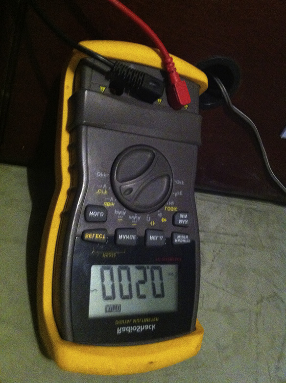
图 5.1 一块仪表。#
你将使用仪表检测的两个最常见信号是电压和电流。设置仪表读取电压时,请记住你要将探头并联连接到要检测的信号上。当读取电流时,仪表必须串联接入电路中。请记住,电流是对流动的测量。几乎所有仪表在读取电压和测量电流时都需要将探头插入不同的插孔。这是因为信号会通过一个内部的分流电阻,在其两端测量电压并按比例换算成电流。
通常,仪表中会有一个保险丝来防止该分流器过载。在某些仪表中,不同的电流量程对应不同阻值的分流器。
所有仪表,无论是在电压模式还是电流模式下,都会对它们接入的电路产生影响。你应该问的是:“影响有多大?”一个典型的数字万用表(DMM)在测量电压时的输入阻抗为 1 到 10 MΩ。当你将探头接入电路时,相当于你向这两个点添加了一个电阻。
我们来看看 图 5.2 中的例子。我们假设我们的仪表具有 10 MΩ 的输入阻抗,并且我们正在测量一个电压分压器电路的输出。
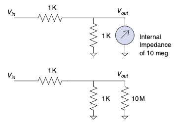
图 5.2 仪表接入一个 1-K 电压分压器的等效电路。#
我们来计算这对电路的影响。首先计算仪表与其连接电阻并联的等效电阻:
嗯,写写画画,咬着铅笔头,自言自语,我刚学过这个法则,是“积除以和”,所以就是 (1 K * 10 M)/(1 K + 10 M),结果是 0.9999 K。
现在我们应用电压分压规则。再哼哼唧唧写写画画一下,发现不接仪表时输出电压是 2.5 V,而接入仪表后输出为 2.4999 V。所以我们大概都同意,这种情况下仪表的影响可以忽略不计。
现在我们改变电阻的取值看看会发生什么。我们将电阻改为 1 MΩ,如 图 5.3 所示。
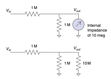
图 5.3 同一个仪表接入一个 1-M 电压分压器。#
你首先应该注意到,不接入仪表时该电路的输出电压和之前是一样的。但接入仪表后会发生什么?1 M//10 M(// 表示并联)等效电阻为 909.09 KΩ。将其代入电压分压规则后,你会得到输出电压为 2.3809 V。你是否看出仪表的影响了?希望你直觉告诉你的是,仪表的影响取决于其阻抗与被测电路阻抗的比值。现在来做一个实验。把 1 M 分压器中的任一电阻改为 1 K,然后重复上述分析。你将发现仪表不再具有显著影响。这是因为电路的整体阻抗约为 1 K。是 Thevenin 告诉我们这个道理的。如果你还没完全理解,那么现在正是回翻第 2 章、复习 Thevenin 等效的好时机。在你评估仪表对电路的影响时,请确保你考虑了被测电路的整体阻抗。
Ahh, the lowly meter—probably the tool you will use most often in your quest for electrical engineering excellence. Most meters you will encounter today fall into the DMM (digital multimeter) category (see Figure 5.1). The first rule of thumb in using a meter (and this applies generally to all the tools you use) is to have some idea of what you are looking for. For example, if you are trying to read an AC signal, don’t set your meter to DC. This might sound overly simplistic, but I believe that poor tool setup is the most common mistake made by the average engineer. You can extrapolate from this rule to solve other misreading problems. This leads to a second rule and a case in point. The rule: Don’t trust auto setups implicitly. The case in point was a motor voltage we were trying to read; the voltage across the motor was a PWM signal with a peak of 140 V. We were trying to read the average voltage across this motor with a Fluke 87, but the readings didn’t make sense (note the application of rule one). We found that when the meter was in auto-range mode, the brain of the meter was confused by the PWM input. Setting the meter manually to the correct range resulted in an accurate and stable reading.
Figure 5.1 A meter.#
The two most common signals you will examine with a meter are voltage and current. In setting up a meter to read voltage, remember that you are hooking the leads up in parallel with the signal you are going to examine. When reading current, the meter must be hooked up in series in the circuit. Remember that current is a measurement of flow. Nearly all meters require you to hook the leads into different plugs when reading voltage than when measuring current. This is so the signal can be routed through an internal shunt resistor across which a voltage is measured and scaled to represent current.
Typically, there is a fuse in the meter to protect this shunt from overload. On some meters the shunt is a different value for different ranges of current.
All meters will affect the circuit they are hooked to, whether they are in voltage mode or current mode. The question you should ask is,“How much?” A typical digital multimeter (DMM) has 1 to 10 M of impedance in the voltage-measuring circuit. As you hook the leads up to the circuit, consider that you are adding a resistor to the same points.
Let’s look at the example shown in Figure 5.2. We will assume that our meter has a 10-MΩ input impedance and we are measuring the output of a voltage-divider circuit.
Figure 5.2 Equivalent circuit of a meter on a 1-K voltage divider.#
Let’s calculate the effect this has on the circuit. We will start by calculating the parallel resistance of the meter and the resistor it is hooked to:
Hmmm, scribble, scribble, nibble on the pencil eraser, mumble to myself, I just learned that rule, it’s the product over the sums, so that would be (1 K * 10 M)/(1 K + 10 M) or 0.9999 K.
Now we apply the voltage divider rule. More humming, more scribbling, and we see that without the meter the output will be at 2.5 V, but with the meter the output will be 2.4999 V. So we will probably all agree that the meter does not have a significant effect in this case.
Let’s change the value of the resistors and see what happens. We will make them 1 MΩ resistors, as shown in Figure 5.3.
Figure 5.3 Same meter on a 1-M voltage divider.#
The first thing you should notice is that without the meter the voltage output will be the same as the previous circuit. But what happens when you hook up the meter? 1 M//10 M (the // marks mean in parallel with) gives a value of 909.09 K. Run that through the voltage divider rule and you get 2.3809 V as the output. Do you see how the meter can make a difference? Hopefully, what your intuition is telling you is that the effect of the meter depends on the ratio of the meter impedance to the impedance of the circuit you are reading. Now try an experiment. Change either resistor in the 1 M divider to 1 K and run through the same analysis. You will see that the meter no longer has a significant effect. This is because the overall impedance of the circuit is about 1 K. Thevenin taught us that. If you don’t quite follow, now is a good time to flip back to Chapter 2 and bone up on Thevenizing. Make sure you consider the overall impedance of the circuit you are measuring when you’re determining the effect a meter will have on your circuit.
示波器#
Scopes
示波器上的两个主要控制就像老电视节目 Outer Limits 中的一句话:“我们控制垂直与水平。” [1]
换句话说,在示波器上你控制的是每格的电压和每格的时间。这里所说的“格”是指屏幕上纵横交错构成网格的刻度线。示波器(o-scope、scope 或 oscilloscope)表示的是电子信号随时间变化的情况。它通过屏幕上的波形轨迹来完成这一点,如 图 5.4 所示。你通过调整每格时间和每格电压的控制项来放大或缩小所看到的线条数据。再强调一遍,这两个控制分别独立实现“缩放”功能。
接下来最重要的控制是捕获模式,即你是看到直流(DC)信号还是 交流 信号。不幸的是,这个控制通常比较隐蔽。它很重要,因为会影响你在屏幕上看到的信号形态。(只需用示波器的 AC 模式读取一个 0 到 5 V 的逻辑信号,你就会明白我的意思。)在 AC 模式下,输入端通过一个串联电容器与示波器的内部电路相连。这会去除信号中可能存在的任何直流偏置。而在 DC 模式下,信号的电压相对于示波器地线保持不变。
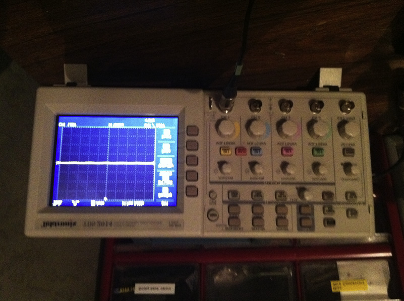
图 5.4 示波器#
在我看来,示波器是电气工程师所拥有的最有用的工具。话虽如此(请想象一声长叹),我见过很多工程师因为误读示波器而误入歧途。这两个事实放在一起说明:了解如何设置好示波器非常重要。
首先提醒一句:永远不要相信示波器的自动设置功能。让我再说一遍:永远不要相信示波器的自动设置功能。[2] 一定要清楚你在寻找什么。比起万用表的自动设置,这一点更重要,因为示波器可能做出更多意料之外的事情。
举个例子,假设你想测量一个信号,它在你按下按钮时从 5 V 变为接地。你连接好示波器,按下自动设置,然后按下按钮。在这种情况下最有可能发生的情况是,示波器将其识别为 5 V 的直流信号,并开始试图捕获某个频率的内容。于是它不断放大,直到你看到一个 60 Hz 的电源交流纹波,振幅约为 10 mV。此时示波器处于 AC 模式,垂直方向为每格 10 mV,水平方向为每格 10 毫秒。别忘了,你本来是想测量一个从 5 V 跳变到 0 V 的信号。自动设置功能完全忽略了你要找的东西。在这个设置下你甚至可能根本看不到那个切换动作,屏幕上还会多出一个 60 Hz 的纹波来扰乱你。
这是我见过的最常见错误之一。一位工程师将示波器接到出故障的电路上,按下自动设置,结果示波器放大了一个无关信号。这位工程师心想:“啊哈,我找到故障点了!”然后整天都在追踪那个根本不重要的问题。
知道自己在找什么是设置示波器时同样重要的规则。问问自己:这个信号会持续多久?你预期的电压范围是多少?从这些设定开始。然后,一旦你能捕获到预期信号,就可以缩放查看细节,比如是否存在恼人的抖动。例如,在我们刚才的例子中,你怀疑按钮存在抖动现象。那就从每格 5 V、每格 500 毫秒开始采集信号。毕竟你是按按钮的人——你到底能有多快?一旦你能稳定捕获该信号,就开始逐步缩放;先把电压调整为每格 2 V 或 1 V,以提高垂直分辨率。然后再调整时间基准。逐步减小每格时间,同时定期查看信号变化。这样你就能引导示波器去观察你想要看的信号。如果你让示波器自动设置,那就像是被绑架、蒙着眼睛到处转。当你摘下眼罩时,你根本不知道自己在哪里,会感到迷失、困惑和不知所措,而这可能导致错误的判断。但如果你是开车的人,就知道自己是如何到达这里的,并对当前状况有更清晰的认识。
所以,设置非常重要。以下是一些你还应该了解的一般事项。
问问自己:“这个信号真的存在吗?”为什么这么问?因为有可能示波器由于其高阻抗特性拾取到一些噪声信号,而这些信号其实并不影响你关注的内容。试试这个:断开探头看看信号是否还在。如果还在,那就很可能是某种辐射噪声,它可能根本不会影响你观察的现象。如果你在处理高功率电路和开关电源,那么各种干扰伪迹层出不穷,虽然不影响实际工作,但很容易被示波器的探头“天线”拾取。
确保你接好了所有接地线(尽管大多数示波器内部已将其短接)。这样做的原因是:流经示波器地线的微小电流可能导致结果错误。你甚至可能误以为自己发现了“自由能”现象。 [3]
在大多数示波器中,接地线都接到了示波器的接地端(出于安全考虑),但这在观察某些参考点不同的信号时可能是灾难性的。此时你可能会通过地线引入电流,这种情况轻则干扰读数,重则损坏设备。如果遇到这种情况,建议使用隔离示波器。
就像使用万用表一样,高阻抗电路也可能受到示波器探头的影响。你是否遇到过这样的问题:问题一旦接上示波器就“消失”了?试试在同样位置接一个 10 兆欧的电阻或 100 皮法的电容。这很可能能解决问题(如果你想知道这些值从哪里来的,它们大致代表了大多数示波器探头的输入阻抗)。
如果一切都无效,那就放下骄傲去读手册吧。是的,我知道这很难,但使用说明书 [4] 往往能为你提供如何正确设置示波器的关键见解,从而让你看到你想看到的内容。
如今的示波器功能极其丰富:炫酷的故障捕获、彩色屏幕(我个人非常喜欢)、放大功能、自动设置(对,这个也有),还有更多。重点是:先正确完成基本设置,这样在你使用其他功能时,才知道自己在做什么。记住:从示波器中获得你想要的信息,取决于你自己——至少在示波器能够读取你的思想之前都是如此。
The primary two controls on a scope are just like in the old TV show, Outer Limits: “We control the vertical and the horizontal.” [1]
In other words, on a scope you are controlling the voltage per division and the time per division. The divisions referred to are the vertical and horizontal marks that make a checkerboard on the screen. The o-scope, scope, or oscilloscope represents the electronic signal over time. It does this with a trace on the screen like the one shown in Figure 5.4. The data you are looking at in terms of this line are magnified or reduced by using the time per division or the voltage per division controls. To reiterate these controls are handling this “zoom” feature independently.
The next most important control is the capture mode, whether you are seeing a DC or an AC signal. Unfortunately, this control is usually somewhat hidden. This control is important because it can affect the way a signal looks on the screen. (Just take a 0 to 5 V logic signal and read it with your scope in AC mode and you will see what I mean.) In AC mode, the inputs are connected via a series capacitor to the guts of the scope. This removes any DC offset the signal might have. In DC mode, the voltage level of the signal relative to the ground lead of the scope is maintained.
Figure 5.4 Oscilloscope.#
The oscilloscope is, in my opinion, the single most useful tool an electrical engineer can have. That said (imagine a big sigh here), I’ve seen a lot of engineers chase down blind alleys because they misread their scopes. Correlating these two facts indicates that it is very important to know how to set up your scope.
First, a word of caution: Never trust the auto setup on a scope. Let me repeat: Never trust the auto setup on a scope. [2] Make sure you know what you are looking for. This is even more important than auto setups on meters because of what the scope might do.
For example, say you want to measure a 5 V signal that switches to ground when you press a button. You hook up the scope, press auto set, and then press the button. The most likely scenario in this case is the scope sees a 5 V DC signal and starts hunting for some frequency to look at. So it zooms in until you see a 10 mV AC ripple from the power supply at 60 Hz. Now you have a scope set to 10 mV per division vertically and 10 ms per division horizontally in AC mode. Remember, you were trying to measure a 5 V DC as it switched to ground on a button press. The auto set totally missed what you were looking for. You probably won’t even see the switch action at this setting and, to top it off, there will be a 60 Hz ripple on the screen to confuse you.
This is the most common mistake I have seen. An engineer hooks up a scope to the misbehaving circuit, hits auto setup, the scope zooms in on an irrelevant signal, the engineer, thinking,“A-ha, I have found the glitch!” spends the rest of the day chasing something that doesn’t matter.
Having an idea of what you are looking for is an equally important rule for setting up a scope. Ask yourself how long the signal will last. What voltage levels do you expect? Start with those settings on your scope. Now, once you are capturing what you expect, zoom in on the details to look for those pesky glitches. Say, for example, you suspect a switch bounce on our earlier example. Start by capturing the signal at 5 V and 500 ms per division. After all, you are pressing this button—just how fast are you? Once you can reliably catch this signal, start working your way in; go to 2 V or maybe 1 V per division to increase vertical resolution. Then start working on the time base. Decrease the time per division while periodically checking the signal you are watching. This way you drive the scope to look at the signal you want to see. If you let the scope do the setup, it is kind of like being kidnapped and driven around blindfolded. When you take the blindfold off, you don’t know where you are. You will be lost, confused, and disoriented, and that can lead to wrong assumptions. If you are the driver, on the other hand, you know how you got there and have a better idea of what is going on.
So setup is important. Here are some other general things you should know.
Ask yourself,“Is the signal really there?” Why? Because it is possible that the scope with its high impedance is picking up noise that really isn’t affecting what you are looking for. Try this: Disconnect the leads. Is the signal still there? If it is, that is a good sign that you are dealing with a radiated noise that might not even affect what you are looking at. If you are working with high-power circuits and switch-mode supplies, there will be all sorts of artifacts that really don’t affect anything but that pick up nicely on the antenna of a scope lead.
Make sure you hook up all your ground leads (even though on most scopes they are tied together internally). The reason to do this is because small currents flowing back through your scope ground can lead to incorrect results. You might even think you have discovered free energy. [3]
On most scopes the ground lead is connected to the Earth ground of the scope (for safety reasons), which can be disastrous when looking at certain signals that may reference to a different point. You can get currents through the ground leg that throw off your reading at best and blow stuff up at worst. If this is happening, get an isolated scope.
Just as with a meter, high-impedance circuits can be affected by the scope leads. Have you ever had a problem go away as soon as you clipped the scope on? Try a 10 Meg resistor or 100 pf cap across the same connections. It is a good bet that will fix the problem (in case you were wondering about where those values come from, they approximate the impedance of most scope leads).
When all else fails, swallow your pride and read the manual. Yes, I know it’s hard, but the destructions [4] usually give you insight into setting up the scope so that you see what you want.
Scopes these days have myriad features: cool glitch captures, colored screens (a personal favorite of mine), magnifications, auto setups (yeah, those too), and much more. The point here is to get the basic setup right so that when you use those other features, you have an idea of what is going on. Remember, getting what you want out of the scope is up to you, at least until they get that mind-reading function working.
逻辑分析仪#
Logic Analyzers
逻辑分析仪与示波器类似,因为它显示的是随时间变化的信号。它在两个主要方面有所不同:第一,它只显示逻辑电平;第二,它具有更多的通道。
可以把逻辑分析仪想象成一种仅限数字信号的示波器。它不会显示处于逻辑高电平或低电平之间的信号。有些逻辑分析仪内置了几个示波器通道,以绕过这一限制,但如果你没有这种设备,请确保你明白自己所看到的是最接近你读取信号的逻辑电平。如果分析仪认为的高电平或低电平与你电路中的电平不同,这可能会导致混淆。如果你怀疑逻辑信号没有达到所需的电压,务必使用示波器检查。
逻辑分析仪最好的特点是拥有众多通道。当你想同时观察数据总线上的八条或更多线路时,这一点非常有用。而用只有几个通道的设备同时观察八个信号几乎是不可能的。
像其他所有功能一样,如果你不了解自己在寻找什么,这个功能也很容易设置错误。不要盲目设置——请大致了解所需的时间基准以找到你要的东西。此外,请记住它是为显示逻辑信号而设计的,可能会掩盖你意想不到的信号电平。
如今,借助数字存储能力,示波器比以往任何时候都更接近逻辑分析仪,而且许多分析仪具有一些类似示波器的功能,使它们比早期设备更像示波器。如果非要分类,我会说示波器是一个更通用的工具,几乎适用于任何情况,除了你需要同时查看大量通道的情况,在这种情况下逻辑分析仪绝对是首选工具。
请记住,使用这个工具(和所有其他工具)时的基本经验法则是:心中要有目标。如果你做到这一点,这将是一种非常有效的工具。
经验法则
始终明确你在寻找什么。
不要相信自动设置。
信号真的存在吗?断开引线看看是否还能接收到信号。
接好所有地线。
电路阻抗越高,越容易被测量工具干扰。
阅读手册!
再强调一次,不要相信自动设置。
A logic analyzer is similar to an oscilloscope in that it displays a signal over a time base. It differs in two main aspects: The first is that it displays only logic levels; the second is that it has many more channels.
Think of a logic analyzer as a digital-only oscilloscope. It is not going to show you signals between a logic high or low. There are logic analyzers with a couple of scope channels built in to get around this limitation, but if you don’t have one of those, make sure that you understand you are seeing the logic level closest to the signal you are reading. If the level the analyzer considers a high or low differs from the level of your circuit, this could lead to confusion. If you suspect that the logic signals are not reaching the required voltages, make sure you check it with a scope.
The best feature of a logic analyzer is the fact that it has so many channels. This becomes very useful when you are trying to observe all eight or more lines on a data bus at the same time. It’s pretty hard to look at eight things at once with only a couple of channels.
This feature, like all the others, is easy to set up wrong if you have no idea what you are looking for. Don’t just set it up blindly—have an idea of the time base needed to find what you are looking for. Also, remember that it is designed to display logic signals, possibly masking signal levels that you might not expect.
These days, with their digital storage capabilities, scopes are closer than ever before to logic analyzers, and the fact that many analyzers have some scope-like capabilities makes them more scope-like than their predecessors. If forced to categorize, I would say that a scope is a more general tool that can be applied in nearly any situation except the one where you need to see a whole bunch of channels at once, and in that case the logic analyzer is definitely the tool of choice. Remember that the basic rule of thumb with this tool, as with all others, is to have an idea of what you are looking for. If you do so, you will find this an effective tool to have at your disposal.
Thumb Rules
Always have an idea of what you are looking for.
Don’t trust auto setups.
Is the signal really there? Unhook the leads and see if you still pick it up.
Hook up all the ground leads.
The higher the impedance of the circuit, the easier it is to disturb with measuring tools.
Read the manual!
And one last time, don’t trust auto setups.
模拟器#
SIMULATORS
首先让我声明:模拟器是很棒的工具(注意转折来了),但我经常看到工程师在使用模拟器时犯下一个重大错误。工程师启动模拟器,尝试自己的想法,设计完成,然后动手搭建真实电路,却发现电路并不像模拟中那样运行。错误就出在这里:太多工程师花大量时间试图弄清电路为何无法正常工作,同时却盲目信任模拟器给出的结果。出于某种原因,一旦电路在计算机上建模,工程师似乎就天生相信模拟器的结果毫无问题。这样做几乎总是会导致极大的挫败感与困惑。你应该铭记这句格言:现实世界不会错;出错的是你的模拟。永远都是如此。如果结果不匹配,那就是你的模拟中存在某些与实验室原型不符的地方。模拟只是现实世界的一个表示,而不是反过来。
First, let me make a statement: Simulators are great tools (here it comes), but too often I see a major mistake made with a simulator. The engineer fires up the simulator, tries out his or her idea, gets it all designed, then proceeds to build a real circuit, only to find the circuit does not work as the simulation did. Here is where the mistake comes in: All too often the engineer spends all his or her time trying to figure out why the circuit isn’t working right while implicitly trusting the simulator to spit out the correct answer. For some reason as soon as the circuit is modeled on a computer, it seems to be an engineer’s nature to trust the result on the simulator without question. Doing so almost invariably leads to immense frustration and confusion. You should take this adage to heart: The real world isn’t wrong; your simulation is. It is always true. If the results don’t match, something in your simulation does not actually represent what is on the prototype in the lab. The simulation is a representation of the real world, not the other way around.
什么才是真实?#
What Is Real?
这并不是说实验台上的电路就是你期望的那样。它可能确实有一个你在模拟中没有的错误。但这并不改变这样一个事实:模拟并没有真正地建模你的设计。
我发现,如果你总是保持质疑模拟结果的态度,会发生两件事。首先,你会直观地理解不同元件如何影响电路。当你反复调整模拟,试图让其与现实世界一致时,你开始理解某个元件的影响到底有多大。其次,你会学会现实世界中元件的局限性——这是单靠数学和公式无法提供的。例如,看看图 Figure 5.5 中电路所使用的 10 微法电解电容。
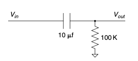
图 5.5 RC 高通滤波器。#
根据你学过的所有公式,这个电路应该能通过所有高于 1/RC 的高频信号。几乎所有模拟器也都能如此模拟,但如果你将这个电路连接到信号发生器,就会发现,当频率升高时,实际效果并不像数学所描述的那样好。数学没有错;只是元件并不完美。
有些模拟器允许你构建等效电路来更准确地表示某个元件。但请记住,这并不意味着工程师可以忽略理解元件局限性的必要性。你确实需要了解实际发生了什么,否则模拟会误导你走向一条无果之路。在使用模拟器时,估算能力极其重要。如果你需要复习“手榴弹技能”,请回到第 1 章。 [5]
This is not to say that the circuit on the bench is what you want it to be. It very well could have a mistake in it that is not in your simulation. However, that doesn’t change the fact that the simulation is not truly modeling your design. I have found that if you take the perspective of always questioning the simulation, two things happen. First, you gain an intuitive understanding of the way different components affect your circuit. As you fiddle with the simulation, trying to get it to match the real world, you begin to grasp how large an effect this or that component has. Second, you learn about the limitations of real-world components—something that just studying math and formulas will not give you. Take, for example, a 10 µf electrolytic capacitor in the circuit shown in Figure 5.5.
Figure 5.5 RC high-pass filter.#
According to all the formulas you have learned, this should pass all the high frequencies above 1/RC you would ever want. Just about every simulator you find will do so, but hook this circuit up to a signal generator and you will find that, as you get up to the higher frequencies, it doesn’t work as well as the math says it should. The math isn’t wrong; it’s just that the component isn’t perfect.
Some simulators will allow you to create equivalent circuits to more accurately represent a given component. Remember, though, that doesn’t negate the need for you as an engineer to understand the limitations of the components. You really need to have an idea of what is going on or the simulation can lead you down a fruitless path. The skill of estimation is immensely important when using a simulator. Skip back to Chapter 1 if you need to brush up on your hand grenade skills. [5]
一个强大的工具#
A Powerful Tool
既然我刚刚批评了模拟器在处理不完美元件方面做得不够好,那我现在就要反过来说一件有趣的事:讽刺的是,它们可能是你拥有的最强大的工具,可以帮助你设计出能很好应对不完美元件的电路。
一旦你真正理解了你所使用元件中可能出现的变化,并建立了一个准确的行为模型,你就能利用模拟器做一件用真实元件很难做到的事:你可以在虚拟空间中建立成千上万个你的设计实例,每个元件在标称值上都有一点点差异。你可以只用点击鼠标就让容差值偏向极限,而不必在抽屉里翻找那个偏离规格下限的元件。如果使用得当,模拟器很可能是你拥有的最佳工具,用来应对元件固有的变化性。
Now that I’ve finished bashing simulators for not dealing well with imperfect components, let me say that, ironically, they are potentially the best tool you have to create a design that handles imperfect components well.
Once you truly understand the variability that can occur in the parts you are using and create an accurate model of what they do, you can do something with a simulator that you cannot do easily with actual parts: You can build thousands of pieces of your design in cyberspace, with each part varying a little from its nominal values. You can swing the tolerances to their extremes with the click of a mouse, saving a hunt through a drawer for that part that is on the low end of spec. If used correctly, a simulator is probably the best tool you have to make your design handle the inherent variability in components.
培养你的直觉#
Develop Your Intuition
使用模拟器最有价值的事情之一,是用它来培养你对基本元件的直觉理解。每个工程师都应该模拟基本的 RC、RL 和 RLC 电路的瞬态响应。尝试改变元件的值,看看会发生什么。
如果你从建模简单电路开始,并且有信心使模型足够准确,当你创建更复杂的模拟时就会更加成功。这和学吉他差不多;你不会一上来就弹出一段连 Eddie Van Halen 都会自豪的即兴段子。你得先学会弹基本和弦。你也应该以同样的方式学会“演奏”模拟器。
尽管很容易上手,也不要一开始就把整个设计组装好然后按“开始”。如果你这么做,我几乎可以保证你会被结果搞糊涂,而且这些结果很可能也是错的。把你的电路拆解成更简单的部分,这些部分你能直观地理解,然后先模拟这些部分。一步一步来。[6] 当你确信你的模型对当前问题来说足够准确地反映了现实世界[7]_,再把这些部分拼接起来,看看会发生什么。
提醒一句:玩模拟器可能非常耗时间。[8] 不要只顾着做模拟,最后却从来没真正搭建过一个实际电路。事实上,如果你不确定电路实际会怎么运行,那就去实验室搭起来看看。当涉及容差分析时,在你开始模拟之前,你应该已经有一个正在运行的真实电路。先用标称值让电路运行起来,再开始研究元件差异会带来什么影响。模拟应该与实验室操作相辅相成。
One of the best things you can do with a simulator is to use it to develop your intuitive understanding of basic components. Every engineer should simulate the transient response of the basic RC, RL, and RLC circuit. Try changing the values of the parts just to see what happens.
If you start modeling simple circuits and getting confidence in making the model accurate, you will be much more successful as you create more complex simulations. It’s not unlike learning to play the guitar; you don’t just sit down and rip out a lick Eddie Van Halen would be proud of. You need to be able to handle the basic chords first. You should learn to“play” a simulator the same way.
Even though it is easy, don’t put together your whole design in the simulator the first time and press go. If you do, I can nearly guarantee you will get confused by the results and they will probably be wrong as well. Break your circuit down into simpler pieces, ones that you can intuitively understand, and simulate those parts first. Eat the elephant one bite at a time. [6] When you are sure your model represents the real world accurately enough [7] for the problem at hand, start knitting those pieces together and see what happens.
One word of warning: Playing around with a simulator can be very time consuming. [8] Don’t get so caught up in doing the simulation that you never get around to building an actual circuit. In fact, if you are unsure as to how the circuit will really work, go build it up in the lab and see. When it comes to tolerance analysis, you should already have a real circuit running in the lab when you start simulating. Get the circuit working with nominal values before you start investigating what component variance will do. Simulation should go hand in hand with lab work.
经验法则(Thumb Rules)
现实世界不会错;错的是你的模拟。
要有信心你的模型能准确代表你的设计。
用估算来交叉验证你的模拟(再加几个“-tion”结尾的词,这就是个绕口令了!)。
通过建模基本电路来培养你对基本元件的直觉理解。
把模型拆解成足够简单、便于校验准确性的部分。然后再把它们组合起来。
模拟应该与实验室操作并行。
设置工具时,心里要有目标:信号有多快?你期望的电压是多少?诸如此类!
The real world isn’t wrong; your simulation is.
Gain confidence that your model accurately represents your design.
Use estimation to double-check your simulation (a couple of more‘-tions’ and this could be quite the tongue twister!).
Model basic circuits to develop your intuitive understanding of the basic components.
Break the model down into pieces that are simple enough to check for accuracy. Then add the models together.
Simulation goes hand in hand with lab work.
When setting up your tools, have an idea of what you are looking for. How fast is the signal? What voltage level do you expect it to be at? Et cetera!
电烙铁#
SOLDERING IRONS
有一天我路过实验室,看到一位技术员站在一位工程师身后观看,那位工程师正把元件焊接到 PCB 上,表现得并不出色。[9] 技术员只说了一句话:“我们这儿是一个工程师在做技术员的工作。”然后他坐下来,娴熟地完成了焊接工作,效果非常出色。
考虑到你可能身边没有一位熟练的技术员,而且我坚信你对产品组装过程了解得越多,就会成为更好的设计者,所以这里我们来介绍一下焊接的基础知识。
I was passing by the lab one day when I saw one of my technicians looking over the shoulder of one of the engineers who was doing a less than spectacular job of soldering components on a PCB. [9] He had but one comment. He said, “What we have here is an engineer trying to do a technician’s job.” Then he sat down and proceeded to do a most excellent job of putting the board together.
On the chance that you might not have a skilled tech at your disposal, and due to the fact that I believe that the more you know about how the product you are designing goes together, the better designer you will be, here we will go over the basics of soldering.
四大基础#
The Basic 4
要焊出好的焊点,需要四个条件:清洁、焊料、助焊剂和热量。
首先,元件要清洁干燥。如果焊盘生锈,通常用一点酒精擦拭就能清理干净。
第二,你需要焊料。焊料是一种铅和锡的混合物,[10] 熔点大约在 100º 到 200ºC 之间,取决于所用的合金。焊料如果使用得当,可以在元件和 PCB 之间形成电气和机械连接。尽管它也起机械连接作用,但请记住它并不是非常牢固的机械连接。
第三,你需要助焊剂。在手工焊接中,助焊剂通常位于焊锡丝的中空核心中。你问,助焊剂是什么?助焊剂是一种在加热时能清洁焊点的化学物质,它能使焊料更好地粘附上去。在某些情况下,助焊剂在焊料之前涂上,例如在波峰焊或焊接槽处理之前。助焊剂有时也叫做松香。
最后,你需要热量。热量是关键所在。焊料会流向热源处。这意味着你需要将元件的引脚加热,以确保焊料流动。在原型制作中,最常见的加热方式是使用电烙铁。推荐这样一个操作步骤:将电烙铁接触焊盘,等焊盘加热片刻,再送入焊锡(参见 Figure 5.6)。如果做得好,你就能避免出现焊料团块;如果你需要学习如何做得更好,请继续阅读。
其他方法还包括热风笔和回流焊炉,但原理是一样的。加热让焊料附着在焊盘和元件引脚上。当一切完成后,一个好的焊点看起来就像 Figure 5.7 中那样。
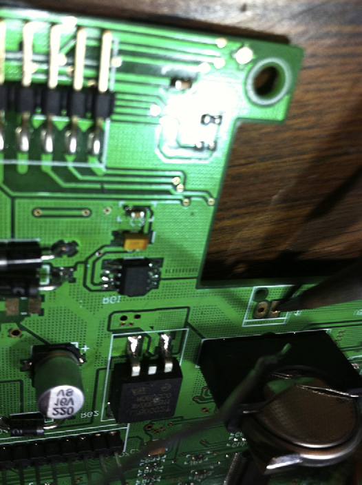
图 5.6 焊料。#
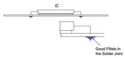
图 5.7 良好的焊点。#
Making good solder joints requires four things: cleanliness, solder, flux, and heat.
First, the parts need to be clean and dry. If the pads are corroded, often a little rubbing alcohol will clean them nicely.
Second, you need solder. Solder is a mixture of lead and tin [10] with a melting point around 100º to 200ºC, depending on the alloy used. When applied properly, solder will provide an electrical and mechanical connection between the part and the PCB. Although it is a mechanical connection, remember that it is not a particularly strong mechanical connection.
Third, you need flux. When hand soldering, this is often inside the solder wire in the hollow core. What is flux, you ask? Flux is a chemical that cleans when you heat it up, preparing the joint so that the solder will stick well. In some cases the flux is applied before the solder, such as before it goes over a solder wave or into a solder bath. Flux is also called resin.
Last, you need heat. Heat brings it all together. The solder will flow to where the heat is. This means that you need to get the leads of the part heated to make sure the solder flows. In prototyping, the typical way you get heat to the part is with a soldering iron. Use a technique like this: You put the iron on the pad, give it a moment for the pad to heat up, then bring in the solder (see Figure 5.6). Done properly you will avoid solder goobers; if you need a lesson on how to do this, read on.
Some other ways are hot air pencils and reflow ovens, but the same thing applies. Heat makes the solder adhere to the pad and the lead of the part. When all is said and done, a good solder joint looks like the one in Figure 5.7.
Figure 5.6 Solder.#
Figure 5.7 Good solder joint.#
焊锡疙瘩#
Solder Goobers
在这四个要素中,通常会引起问题的是热量的施加,尤其是在使用电烙铁时。元件和印刷电路板(PCB)都对热量敏感。过高的热量会损坏元件,而PCB焊盘是通过熔点低于焊锡的胶水粘附在PCB上的。 [11] 过多的热量持续过久会造成不良后果。元件可能会损坏,焊盘或走线可能会被掀起(当胶水融化时)。
另一方面,热量不足也会导致故障。其中一种故障被称为冷焊点。当焊接时没有让两个接合部件都获得足够的热量,就会发生这种情况。此时焊锡会附着在一个部件上而不是另一个部件上。没有获得足够热量的部件将无法获得良好的连接。这就是所谓的“冷焊点”。它看起来如 图5.8 所示。
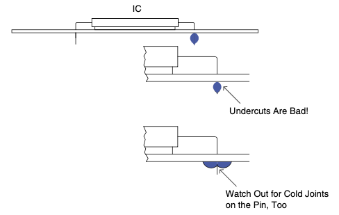
图5.8 冷焊点。#
冷焊点是使用电烙铁时最常见的故障。你可能动作太快,没有让热量在焊点停留足够久,或者只接触了焊盘而没有接触到元件引脚。一个手工焊接时的经验法则是将烙铁尖放在焊点上,默数“一密西西比”,然后施加焊锡,稍等片刻,再移开烙铁。
还有两件事你需要做才能让你的电烙铁保持良好状态。一是确保烙铁头上有镀锡。如果电烙铁长时间通电,烙铁头上的焊锡和助焊剂会蒸发,留下干燥的烙铁头。干烙铁头传热性能不如带有焊锡的烙铁头好。在使用前在烙铁头上加一点焊锡称为镀锡。(你也可以对导线进行镀锡,使其更易焊接到连接点。)如果你发现热量难以传导到部件上,可以尝试加一点焊锡来帮助传热。
第二件事是要经常清洁烙铁头。任何一把像样的电烙铁都会在托盘里配有湿海绵。用海绵擦拭烙铁头可以有效清洁它。清洁烙铁头可以防止多余的助焊剂堆积干扰焊接过程。提示:不要将海绵泡得太湿,也不要在海绵上过度擦拭烙铁头。过多的水分或过久的擦拭会导致烙铁头温度过低,影响下一个焊点的焊接。不要忘了在焊下一个焊点之前再次给烙铁头镀锡。
Of these four items, the one that usually causes problems is the application of heat, particularly when you are using a soldering iron. Parts and PCBs are both sensitive to heat. The parts can be damaged by too much heat, and the PCB pads are adhered to the PCB with glue that has a lower melting point than solder. [11] Too much heat for too long can be bad. Parts can be damaged and pads or traces can be lifted (when the glue is melted).
The flip side is that not enough heat will lead to failures. One of these failures is called the cold solder joint. This happens when you do not get enough heat to both parts being joined. When this happens, solder will adhere to one part and not the other. The part that did not get enough heat will not get a good connection. That is why it is said to be a cold joint. It looks like Figure 5.8.
Figure 5.8 Cold solder joint.#
A cold solder joint is the most common failure of using a soldering iron. You get going a bit too fast and don’t leave heat on the joint long enough, or you only touch the iron to the pad and don’t get it on the lead of the part. A good rule of thumb when soldering by hand is to place the tip of the iron on the joint, count “one Mississippi,” and then apply the solder, wait a moment, and remove the iron.
There are two other things you need to do to keep your soldering iron working right. One is to make sure the tip is tinned. If an iron is left on for some time, the solder and resin on the tip will evaporate, leaving a dry tip. A dry tip will not conduct heat to the parts you touch as well as a tip with solder on it will. Applying a little solder to the tip before using it is called tinning. (You can also tin wires to make them easier to solder to a connection.) If you are having a problem getting heat to a part, try adding a little solder to help conduct the heat.
The second thing you need to do is clean the tip of the iron often. Any decent soldering iron will have a sponge in a tray with water. Wiping the tip on it will effectively clean it. Cleaning the tip keeps the buildup of excess flux from interfering with the soldering process. A word of caution: Don’t soak the sponge with too much water, and don’t rub the iron on the sponge excessively. Too much water or rubbing it too long will cause the tip to cool down too much, affecting the next joint you need to apply solder to. Don’t forget to tin the tip before going on to the next joint.
表面贴装(SMT)注意事项#
SMT Specifics
在今天这个时代,你很可能会接触到表面贴装元件的乐趣。尽管看起来几乎无法手工完成,其实并没有想象中那么糟。我建议你使用焊锡膏;你只需将焊锡膏涂在引脚和焊盘上。然后用电烙铁进行一次时机良好的扫动,就能把所有引脚焊接好,形成非常漂亮的焊点。这需要一定的练习,所以第一次尝试时请准备好会用掉一些元件甚至PCB。焊锡膏太多会造成引脚之间短路,太少又会焊不上。当你掌握了正确的焊锡膏量和电烙铁的时间控制,焊锡就会流向正确的位置,达到你想要的效果。 [12]
In today’s world you will likely be treated to the fun of surface-mount components. Though seemingly impossible to do by hand, they are not as bad as they might seem. I recommend you use solder paste; you basically paint the leads and the pads with the paste. Then with a nicely timed sweep of the solder iron you can get all the leads connected with some very pretty joints. It takes some practice, so be prepared to go through a few parts and possibly PCBs the first time you attempt it. Too much paste and you will get shorts across the leads, too little and you get no connection. When you get the right amount and the right timing of the iron, the solder flows to the right places and does just what you want. [12]
无铅焊接#
Lead Free
过去几年里,一些标准开始强制要求几乎所有产品都使用无铅焊锡。结果发现铅其实是让焊接更容易的一种好东西。无铅焊锡材料相比旧的含铅焊锡更难伺候。其最佳工作温度范围更窄,而且在我看来,为了形成良好的焊点所需的加热时间也更长。总体而言,它的附着力似乎也不如含铅焊锡好。
Over the last several years some standards have been implemented requiring lead-free solder in almost all products. Turns out lead was a nice thing for making soldering easier. The lead-free materials are a bit more finicky than the old leaded type. The temperature range that works well is narrower, and it seems to me that the amount of heat needed to get a proper joint takes longer. All in all it just doesn’t seem to stick as well.
拆焊#
Desoldering
除非你从不犯错,否则在你的职业生涯中某个时刻,你必然需要拆除已经焊接在PCB上的元件。拆焊可能是一种令人沮丧的经历。你最可能在拆焊时掀起焊盘、烧伤手指,甚至爆粗口。希望我能分享一些技巧,避免在你拆焊时空气变得“蓝色”。我们还将讨论三种主要的拆焊工具:吸锡带、手动吸锡器和拆焊台。
- 提示 1.
如有可能,牺牲元件。如果你不需要回收拆下来的元件,剪断引脚(这样你就不必一次性拆除一个40引脚的元件)将大有帮助。剪断所有引脚,一次处理一个引脚。曾经我们遇到过需要保留40引脚元件但不需要PCB的情况。我们的解决方案是?将电路板拿到车间,用喷灯快速加热PCB背面,同时用钳子从另一侧把元件拉下来。这招很管用,而且烧毁的PCB后来还成为了向管理层开玩笑的绝佳素材!
- 提示 2.
给元件添加焊锡。添加焊锡有助于将热量传导到你要拆除的焊点。拆除元件的诀窍就是要快速将热量传到所有必要的位置。例如,你可能需要移除一个径向电解电容。这种元件的两个引脚靠得很近。你实际上可以在引脚间形成一个焊锡桥,同时加热两个引脚,从而快速拔下元件。
- 提示 3.
先把元件和引脚取下,再考虑去除焊锡。先加热、拉下元件,然后再回来清除焊孔里的焊锡。通常当你试图在取下元件之前完全去除焊锡时,会发现还有一小段焊锡仍然将引脚粘在通孔的一侧。问题在于,这段焊锡太小,难以加热以松开引脚。此时参考提示2,再试一次。
Unless you never make a mistake, at some time in your career you will need to remove a part that has been soldered to a PCB. Desoldering can be a frustrating experience. It is during desoldering that you are most likely to lift a pad from a PCB, burn your fingers, and possibly cut loose with a few expletives. Hopefully, I can share some hints to keep the air from turning blue when desoldering is required of you. We will also discuss the three main tools for lifting solder: solder tape, hand pumps, and desoldering stations.
- Hint 1.
Sacrifice the component if possible. If you do not have to salvage the part you are taking off, clipping the leads (so that you are not trying to remove a 40-pin part all at once) is a great help. Cut all the leads and deal with one pin at a time. Once we had a situation where we needed the 40-pin part but not the PCB. What was our solution? Take the board down to the shop and hit the back of the PCB with a quick burst from a blowtorch while yanking the part off of the other side with a pair of pliers. It worked like a charm, and the burnt PCB made for a great joke on management later!
- Hint 2.
Add solder to the part. Adding solder can help you conduct heat to the joint you are trying to dismantle. The trick to getting the part off is to get heat quickly to all the places you need to. For example, you might need to remove a radial electrolytic capacitor. On this part both leads are close together. You can actually create a solder bridge between the leads and get heat to both leads at the same time and quickly pull the part off.
- Hint 3.
Get the part and pin off before you worry about getting the solder off. Apply heat, yank the part, then come back and get solder out of the hole. Often when you are trying to get the solder completely off before taking the part off, you will find that a small piece of solder still holds the lead to the side of the via. Trouble is that it is such a small piece of solder that it is difficult to heat it up to get the lead loose. Apply hint 2 and try again.
焊带#
TAPE
焊带是一种铜编织带。铜是一种极好的导热体,当加热时,会将焊锡吸入编织带中。重要的是要先将热量施加到编织带上,然后将编织带压在焊锡上。如果你只是把编织带插入熔化的焊锡中,而不先加热它,焊锡只会停留在那里。记住,焊锡会流向热源。
还要注意,编织带是由铜制成的,而铜会氧化。一旦氧化,焊锡就很难粘附在上面,因此旧的焊带基本上没什么用。不过新的焊带效果很好,而且便宜又方便使用。
Solder tape is a copper braid. Copper, being a great conductor of heat, will wick the solder into the braid when heated up. It is important to apply the heat to the braid and then press the braid on the solder. If you just try to stick the braid in the mol- ten solder without heating it up, the solder will just sit there. Remember, solder flows to heat.
Also note that the braid is made of copper, and copper can tarnish. Once it has tarnished, solder will have a hard time sticking to it, so old solder tape is pretty much useless. New tape works well, though, and is cheap and convenient to use.
手动吸锡器#
HAND PUMP
我个人偏爱的工具是手动吸锡器,它使用方便,价格相对便宜,且易于维护。在使用手动吸锡器时,先按下活塞,加热你想移除的焊锡,然后按下按钮,“唰”的一声,焊锡就像意大利面条一样被吸进去了。确保烙铁加热足够时间,使焊锡在过孔中完全熔化。你可能需要应用第二个提示来帮助操作。使用手动吸锡器最大的缺点是,如果需要大量拆焊,会导致拇指酸痛。
My own tool of choice, the hand pump, is easy to use, relatively inexpensive, and easy to maintain. When using the hand pump, you press down the plunger, heat up the solder you are trying to remove, press the button, and thwoop, in goes the solder like a spaghetti noodle. Make sure you leave the iron on long enough for the solder to become molten clear through the via. You might need to apply hint 2 to help things out. The biggest downside to the solder pump is the sore thumb you are going to get if you need to do a lot of desoldering.
CHIP QUIK#
CHIP QUIK
我最近发现了一种叫 Chip Quik 的产品(见 www.chipquikinc.com),这是一种在加热并与焊锡混合后能让焊锡在较长时间内保持液态的焊料/金属材料,这样你就有机会移除你正在处理的元件。这是一种非常巧妙的方法,尤其适合移除带有许多引脚的芯片,尤其是你想要保留的表面贴装版本。对于处理大量器件来说,这种方法成本并不低,但在某些情况下,它正是你所需要的。
I recently discovered a product called Chip Quik (see www.chipquikinc.com) that is a type of solder/metal that when heated and mixed with solder keeps it in a fluid state for a long period of time, giving you the chance to remove the part you are working on. This is a really slick way to pull off a chip with a lot of leads, especially SMT versions that you are trying to save. It’s not a super cheap solution if you are doing a lot of parts, but in some cases it is just what you need.
拆焊站#
DESOLDERING STATION
如果你需要进行大量拆焊,并且预算充足,那这就是你需要的工具。拆焊站是手动吸锡器的电动版。烙铁与吸力装置集成于烙铁头,在吸出焊锡时提供真空。通常需要定期维护这些工具。由于焊锡移除过程具有腐蚀性,烙铁头可能会磨损。如果使用不当,它们也很容易堵塞。始终侧向吸,不要垂直吸。熔化的焊锡有重量,侧向移动比垂直提起更容易。焊点清除后继续吸几秒钟,以确保熔化的焊锡完全进入吸锡枪的收集腔内,从而避免在喷嘴中途固化。
如果维护得当,这是从PCB上移除焊锡最快最简便的方法。也可以在引脚仍在位置上的情况下将器件移除。这可以通过在吸锡时做小的圆周运动,使引脚与过孔脱离接触来实现。然而,如果可以牺牲该器件,这通常是更容易的做法。
If you need to do a lot of desoldering and you have some cash to spend, this is a tool you need. The desoldering station is a powered version of the hand pump. The iron is integrated into the tip, where a vacuum is applied to suck out the solder. Generally you need to maintain these tools regularly. The tips can wear due to the corrosive nature of the solder removal. They can get plugged easily when they’re not used properly. Always suck to the side, not straight up. The molten solder has weight, and trying to move that to the side is easier than trying to lift it straight up. Keep sucking for a couple of seconds after the joint is clear to make sure that the molten solder gets all the way into the receptacle in the gun so that it doesn’t solidify midway through the nozzle.
Properly maintained, this is the quickest and easiest way to get solder off a PCB. It is also possible to get a part off with the pin still in place. This is done by using a small circular motion to get the pin out of contact with the via as you are sucking the solder. However, it is still easier to sacrifice the part if that is possible.
Thumb Rules(Thumb Rules)
焊锡会流向热源。
焊锡会流向热源。
如果你还没明白,再记一次:焊锡会流向热源!
施加热量时数1秒以防止冷焊点。
在使用烙铁前先进行镀锡。
对于表贴器件,使用恰当量的焊膏和恰当的加热时间。
经常清洁烙铁头。
熟能生巧。
在拆焊时,尽可能牺牲器件。
加焊锡以促进热传导。
先将器件和引脚移除,再考虑如何清除孔内焊锡。
使用拆焊站时,通过小的圆周运动帮助清除引脚和过孔之间的焊锡。
Solder goes where the heat is.
Solder goes where the heat is.
And if you didn’t get it this time, remember: Solder goes where the heat is!
Prevent cold solder joints by counting 1 second while applying heat.
Make sure that you tin the iron before using it.
Use just the right amount of solder paste with SMT parts and just the right amount of time.
Clean the tip often.
Practice makes perfect.
When desoldering, sacrifice the part if possible.
Add solder to promote heat flow.
Get the part and pin off before worrying about getting the solder out of the hole.
A small circular motion with a desoldering station tip will help clear the solder from the lead and the via.
人员工具#
PEOPLE TOOLS
当我第一次进入职场时,有一段经历至今让我记忆犹新。前台打来电话,说:“某某人来找你。他想知道你是否可以和他共进午餐。”当然,我当时想的是:“嘿,有免费的午餐吃,但这个似乎和我很熟的人到底是谁?”
于是,就在吃着玉米片和 arroz con pollo 的过程中,我一头扎进了我的第一次与销售代表、分销商和现场应用工程师(FAE)打交道的经历。
午餐挺不错。点菜不成问题,但要弄清楚这三类人的角色,比吃几个塔可饼要难得多。谁负责什么、对普通“迪尔伯特”员工意味着什么,这些都挺让人困惑的。所以我觉得给你一点关于这些人做什么、以及他们能如何帮助你的了解也无妨。
首先,这些人都与生产你所需产品的公司有某种关系,不论是集成电路、晶体管、微处理器还是别的什么产品。这里我说的“公司”,是指拥有产品并负责销售的公司,不是你就职的公司。
When I entered the professional realm for the first time, I had an experience that I still remember. I got a call from the receptionist. She said,“So and so is here to see you. He wants to know if you can have lunch with him.” Of course I’m think- ing,“Hey, free food, but who is this guy who seems to be my instant friend?” Thus, it was over nacho chips and arroz con pollo that I tumbled headlong into my first experience in the world of reps, distributors, and FAEs.
Lunch was good. I had no problem figuring out what to order from the menu, but getting to understand the roles of these three people took more than a few tacos. It can be a bit confusing as to who does what and what that means to the average“Dilbert” out there, so I figured it wouldn’t hurt to give you some idea of what these guys do and how they can help you.
First, all these people have some relationship to the company that makes the product you need, whether an IC, transistor, micro, or whatever. When I say company in this case, I am referring to the company with the product to sell, not the company you work for.
公司#
The Company
销售你感兴趣的零件的公司,会雇用多个层级的人员将产品展示给你,并最终销售给你。公司内部也有销售人员和管理人员,如果你和他们密切合作,也许会认识他们。你与他们的合作密切程度,通常取决于你能带来的业务量或潜在业务量。
如果你能认识公司内部的某个人,那绝对是好事。现在这些人比以往任何时候都更容易接触到,如果你需要了解一个元件在某种奇怪情形下的表现,找那个实际设计这个元件的人沟通无疑是最好的选择。
The company selling the widget you are interested in employs several layers of people to get its product in front of you and sold to you. It also has internal salespeople and managers you might get to know if you work closely with them. How closely you work with them often depends on the amount of business or potential business you represent for them.
If you can get to know someone on the inside, it is never a bad thing. These guys are more accessible now than ever, and if you need to know how a part will act in some weird situation, talking to the person who actually designed the part is definitely the best option.
销售代表#
The Rep
离公司稍远的一层是销售代表。 [13] 他或她代表生产该元件的公司来销售给你。通常销售代表并不直接从该公司领取薪水,而是由代表该公司的销售代理公司支付薪酬。这些代表或他们所在的公司,通常会按照他们所创造的销售额提取一定比例的佣金,通常是 1% 到 5%(视销售量和其他一些复杂的公式而定,这些公式旨在让生产产品的公司尽可能少地付出成本,同时尽可能多地推动销售)。
销售代表会与分销商合作安排元件交付、为你提供样品等。他们非常希望你使用所代表公司的产品,几乎不会推荐其他解决方案,因为他们的收入与该公司的产品绑定。销售代表通常不得同时代表互为竞争关系的公司。就我所见,我们所说这些面向“迪尔伯特”产品的销售代表,很多都有某种工程背景。 [14]
One layer removed from the company, you will find the rep. [13] This is the per- son who represents the company making the part it wants to sell to you. He or she does not usually draw a salary directly from the company. Reps are paid by the rep firm that represents the company. The reps and/or their firm are typi- cally rewarded for their efforts with some percentage of the sales they make, usually 1 to 5% (depending on volumes and other complicated formulas designed to cost the company making the product the least amount of money yet drive sales as much as possible).
The reps will work with the distributor in scheduling parts, getting you samples, and other such stuff. They are very interested in you using the company’s widget, and it is unlikely they will offer an alternate solution since they’re monetarily tied to the company’s widget. Reps typically are not allowed to represent competing firms. My experience is that reps for the Dilbert-esque products we are talking about often have an engineering background of some type. [14]
分销商#
The Distributor
“分销商和销售代表的区别是什么?”我曾问过其中一人。他答道:“大概 15% 吧。”
分销商会储备库存,并在原价基础上加价以覆盖他们的支出。他们通常能从每个元件中赚取大约 20% 的利润,但这只是个大致数字。实际利润会因不同的商务协议而千差万别。有些制造商会要求分销商维持某些特定利润率,作为他们代理其产品的前提。
某个大型分销商时刻关注市场趋势,喜欢采购那些未来可能会变得稀缺但仍有需求的产品。 [15] 然后他们会大量采购,屯在库里一段时间,再高价出售以获取利润。
有些公司使用独家分销商,有些公司则采用多渠道销售。在采用多个分销商的情况下,谁先“注册” [16] 某个元件在某个应用中的使用,谁就能以更低的价格获得该元件。这是为了奖励那些积极拓展业务的分销商。
分销商最大的优势是供应链管理。通过为你缓冲库存,他们能帮助你应对订单规模的波动,尤其是在订单突然增加时,能有效缩短交货周期。
他们不太可能只绑定某一厂商,通常会为同一个问题提供多种解决方案。他们倾向于推荐既能解决你问题又对他们利润最大化的产品。分销商通常没有工程背景。希望他们中的很多人能买这本书看一看,并且不会因为我揭露了这个看似神秘的世界而感到不快。
“What is the difference between the distributor and the rep?” I asked one of these guys once.“About 15%,” I was told.
Distributors will stock parts and mark up the cost to cover the money they have expended. They tend to make about 20% on a given part, but that is just a ballpark figure. The actual number can be all over the place, depending on the particular business agreements. Some manufacturers force distributors to specific margins if they carry their parts.
One of the biggest distributors out there watches market trends constantly and looks to buy stuff that is likely to become rare yet needed in the future. [15] Then they go out and buy a whole bunch of said item, sit on them for a bit, and sell them at a profit later.
Sometimes companies use exclusive distributors. Some use multiple channels. In the case of multiple distributors, whoever is the first to register [16] a part for a particular application gets a lower price on the part than any of the other distributors. This is designed to reward the distributors for getting out and getting more business.
The biggest advantage of a distributor is supply-chain management. By buffering stock for you, they can help handle ups and downs in order sizes, shortening lead times when orders go up unexpectedly.
They are less likely to be tied to a particular manufacturer of a part, and they often carry multiple solutions to a given problem. They will tend to lead you to the part that will solve your problem and be the most profitable for them. Distributors are less likely to have an engineering background. Hopefully many of them will buy this book and not be upset that I disclosed so much about this seemingly secret world.
FAE(现场应用工程师)#
FAEs
你迟早会接触到 FAE,不论是分销商、销售代表,还是产品公司派出的。FAE 扮演着多个角色。他们是帮你把产品调试成功的主力。他们也会分析你的应用需求,并提出可能适合的元件建议。最后,FAE 往往充当你与分销商之间的翻译桥梁。你可能也知道,一旦电子工程师开始讲技术细节,就很难听懂了。
对很多“迪尔伯特”来说,FAE 这份工作堪称完美。他们可以提出各种解决方案,却不必承担最终实现的责任。有时我也梦想着做 FAE,就是因为这个原因。但另一方面,FAE 很少能看到最终成品,也就失去了“虽然迟了、超预算了,但终于搞定了!”那种满足感。
FAE 经常参加公司组织的培训,以深入理解产品工作原理。他们通常认识公司内部的工程师,或者可以迅速联系到他们来帮你解答问题。现在越来越多的公司为了推动产品销售,不仅开发新产品,还开发针对这些产品的应用。FAE 和公司工程师常常会被安排设计一些小巧实用的演示应用,来展示产品的优越性能。要记住,对他们来说,这就像是在学校实验室——只要演示时能成功运行一次就好。而正式的量产就完全是另一回事了,所以你必须做好功课,彻底测试 FAE 的设计再考虑是否投入量产。
Working for distributors, reps, or even the company, you will sooner or later run into the field application engineer (FAE). The FAE plays several roles. He is the main person who helps you get the part to work. He or she also looks at your application and often will suggest parts that might be a good fit. Lastly, FAEs often act as translators between you and the distributor. As you might well know, it can be difficult to understand an EE when he or she gets into technical details.
For many a Dilbert, the FAE has the perfect job. The FAE gets to come up with all these solutions but has no responsibility for actually making it work at the end of the day. There have been days I have dreamed of being an FAE for just that reason. However, the flip side is FAEs also rarely see the finished product and miss out on the satisfaction of the“being late and over budget, but whew! It’s finally done” feeling.
FAEs often go to a lot of training sessions with the company to understand how the part works. They usually know or can contact the engineers in the company to help answer questions. More and more, in an effort to sell their parts, companies are not only developing new parts but also creating applications for those parts. FAEs and company engineers are often tasked with coming up with cool little application demos and the like that show you how great the part is. Remember, though, for them it is like lab back in school—they only need it to work that once when they are showing it. Production runs can be a whole other matter, so do your homework and test an FAE design thoroughly before you commit to it on a full production run.
设计胜利#
Design Wins
当分销商向销售代表以及公司“注册”某个元件,并且这个元件最终确实被用在了设计中,这就叫做“设计胜利(design win)”。这是个在吃开胃菜时经常听到的术语。奇怪的是,工程师们用的词其实都挺有道理,对吧?
记住,谁注册了元件,谁就能拿到更低的价格。通常这让他们的报价比其他分销商更有竞争力。我说的是“通常”,因为我也见过未注册分销商报出更低价格的情况,尽管很少见。
还有一种情况是可以“转移注册”。如果你实在不愿意跟某个分销商合作,而且你对公司而言是个大客户,他们可能会把注册转移给你更喜欢的分销商。不过这是非常罕见的,通常是为了安抚客户而做出的最后手段。如果这种情况太频繁,原本鼓励抢先注册的机制就会失效。
When the distributor registers a part with the rep and thus the company and then the part actually gets used in the design, it is called a design win. This is a common term that’s heard often over appetizers. Odd how engineer types use words that make sense when you think about it, isn’t it?
Remember, whoever registers the parts gets a discount on that item. That usually makes their price hard to beat compared to other distributors. I say usually because I have seen a lower price quoted from an unregistered distributor, albeit rarely.
Another thing that can happen is that registration can be moved. If you really don’t like working with the distributor and you are a big enough customer to the company, they can move the registration to a distributor you prefer. However, this is rare and usually done as a last resort to appease the customer because if it happened too much, all incentive to get their part in the door first dries up.
直接采购#
Going Direct
根据你的订单规模,有时你可以考虑“直接采购”。这意味着你将绕过分销商,直接向公司购买产品,目的自然是获得更低的价格。
但这样做也有很多弊端。公司通常会设定最小订单量、较长的交货期以及相对不利的条款。如果你的订单规模较小,他们可能根本不会考虑接受。
在你决定直接采购前,务必要权衡各种选项,因为你将移除一部分设计和供应管理中所依赖的支持体系。
有些公司甚至根本不允许你直接采购,他们的政策就是只能通过分销渠道。但我知道他们也会控制分销商的最终报价,以保证在市场中具备竞争力。
Depending on the size of your orders, one thing that you might consider is going direct. This means that you will buy parts directly from the company, skipping distribution. The goal is to get a lower price.
The cons to this approach are several. The company will usually have minimum orders, lead times, and terms that are less favorable than working with a distributor, and if you are a little guy (order wise) they probably won’t even consider it.
Before you do this, consider the options carefully, because you will be removing a piece of the support structure that you use in the design and supply manage- ment of the part.
There are companies that will not even allow you to go direct; they have a pol- icy of distribution only. However, I happen to know that they also dictate to those distributors what the final price will be to keep them competitive in the marketplace.
总结#
To Sum It Up
要让元件送到你手中,背后是一个由多方组成的体系。每一方都希望分得一杯羹,并提供相应的服务来证明他们的价值。了解谁负责什么,能让你更有效地与这些“人员工具”协作,以完成你的工作。
就我的经验来说,那些比较成功的销售代表、分销商、FAE 等等,通常会频繁拜访你,了解你在做什么,并在接触到新技术和新思路时及时通知你。他们会提出建议、提供解决方案,当然,有时还会请你吃顿午餐。
There are several legs to the stool of getting parts to you. Each leg wants his piece of the pie and has services to provide to justify their cut. Knowing who does what will enable you to better work with these“people tools” to succeed at your job.
In my experience, the more successful reps, distributors, FAEs, and the like will visit you often enough to know what you are working on and keep you in mind as they see new technologies and ideas that you can use. They will have suggestions and solutions and, yes, they might even buy you lunch once in a while.
经验法则(Thumb Rules)
销售代表受公司合同雇佣。
分销商作为独立实体运营。
FAE 知道产品怎么工作。
公司想把它的酷产品卖给你。
有时你可以让公司和 FAE 协助完成部分设计工作。
所有这些人员工具都可以帮助你找到元件并获取报价;他们相互协作,力求提供最优服务。
The rep works for the company under a contract.
The distributor works as an independent.
The FAE knows how the stuff works.
The company wants to sell you a cool widget.
Sometimes you can get the company and the FAE to help do some of the design work.
All these people tools can help you find parts and get quotes; they work together to provide the best service they can.