3.2 复用与解复用#
3.2 Multiplexing and Demultiplexing
在本节中,我们将讨论传输层的复用与解复用,即将网络层提供的主机到主机的传送服务扩展为运行在主机上的应用进程之间的进程到进程传送服务。为了使讨论具体化,我们将以互联网为背景来讲解这一基本的传输层服务。但我们强调,所有计算机网络都需要复用/解复用服务。
在目的主机上,传输层从下方的网络层接收报文段。传输层的职责是将这些报文段中的数据交付给主机中相应的应用进程。让我们来看一个例子。假设你正坐在计算机前,一边下载网页,一边运行一个 FTP 会话和两个 Telnet 会话。因此,你运行了四个网络应用进程——两个 Telnet 进程,一个 FTP 进程,一个 HTTP 进程。当你计算机中的传输层从网络层接收到数据时,它需要将接收到的数据定向到这四个进程中的一个。现在让我们看看这个过程是如何完成的。
首先回忆 第 2.7 节 中提到的,一个进程(作为网络应用的一部分)可以拥有一个或多个 套接字(socket) ,这些套接字是数据从网络传递到进程,或从进程传递到网络的通道。因此,如 图 3.2 所示,接收主机中的传输层实际上并不是将数据直接传递给进程,而是传递给中间的套接字。因为在任何时刻,接收主机中都可能存在多个套接字,所以每个套接字都有一个唯一的标识符。该标识符的格式取决于是 UDP 套接字还是 TCP 套接字,我们将在后文中详细讨论。
现在让我们来看看接收主机如何将传入的传输层报文段定向到合适的套接字。每个传输层报文段都包含了一组用于此目的的字段。在接收端,传输层检查这些字段,以识别接收套接字,然后将报文段定向到该套接字。将传输层报文段中的数据交付给正确套接字的过程称为 解复用(demultiplexing) 。而在源主机中从不同套接字收集数据块、为每个数据块添加首部信息(以后将在解复用中使用)以构建报文段,并将报文段传递给网络层的过程称为 复用(multiplexing) 。请注意,图 3.2 中的中间主机中的传输层必须将来自下层网络层的报文段解复用到上层的 \(P_1\) 或 \(P_2\) 进程中;这是通过将到达报文段中的数据定向到相应进程的套接字来完成的。中间主机的传输层还必须从这些套接字收集输出数据,形成传输层报文段,并将其传递到下层网络层。尽管我们是在互联网传输协议的上下文中引入复用与解复用的,但重要的是要认识到:当某一层的单个协议(无论是传输层或其他层)被上一层的多个协议使用时,这都是需要考虑的问题。
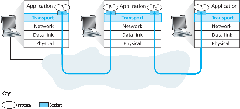
图 3.2 传输层的复用与解复用
为了说明解复用的过程,我们回顾上一节中的家庭类比。每个孩子都由其名字唯一标识。当 Bill 从邮递员那里收到一堆邮件时,他通过观察信件的收件人是谁来执行解复用操作,然后将信件亲自分发给他的兄弟姐妹。而 Ann 在收集兄弟姐妹的信件并将邮件交给邮递员时则执行了复用操作。
现在我们理解了传输层复用与解复用的作用,让我们看看主机中是如何具体实现的。从上面的讨论我们知道,传输层复用要求:(1) 套接字具有唯一的标识符;(2) 每个报文段包含用于指示应交付给哪个套接字的特殊字段。这些特殊字段如 图 3.3 所示,即 源端口号字段 和 目的端口号字段 。(UDP 和 TCP 报文段还有其他字段,这将在本章后续小节中讨论。)每个端口号是一个 16 位数字,范围从 0 到 65535。端口号范围中的 0 到 1023 被称为 知名端口号(well-known port numbers) ,是受限制的,也就是说它们是为诸如 HTTP(使用端口号 80)和 FTP(使用端口号 21)等知名应用协议保留的。知名端口号的列表见 RFC 1700 ,更新版本可在 http://www.iana.org 上获取 RFC 3232。当我们开发新应用程序时(比如 第 2.7 节 中开发的简单应用),我们必须为应用分配一个端口号。
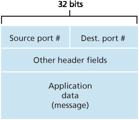
图 3.3 传输层报文段中的源端口号与目的端口号字段
现在应该清楚传输层 可以如何 实现解复用服务:主机中的每个套接字被分配一个端口号,当报文段到达主机时,传输层检查该报文段中的目的端口号,并将其定向到相应的套接字。然后报文段中的数据通过套接字进入附属进程。正如我们将看到的,这基本上就是 UDP 的做法。不过,我们还会看到 TCP 中的复用/解复用机制要更为复杂一些。
In this section, we discuss transport-layer multiplexing and demultiplexing, that is, extending the host-to- host delivery service provided by the network layer to a process-to-process delivery service for applications running on the hosts. In order to keep the discussion concrete, we’ll discuss this basic transport-layer service in the context of the Internet. We emphasize, however, that a multiplexing/demultiplexing service is needed for all computer networks.
At the destination host, the transport layer receives segments from the network layer just below. The transport layer has the responsibility of delivering the data in these segments to the appropriate application process running in the host. Let’s take a look at an example. Suppose you are sitting in front of your computer, and you are downloading Web pages while running one FTP session and two Telnet sessions. You therefore have four network application processes running—two Telnet processes, one FTP process, and one HTTP process. When the transport layer in your computer receives data from the network layer below, it needs to direct the received data to one of these four processes. Let’s now examine how this is done.
First recall from Section 2.7 that a process (as part of a network application) can have one or more sockets, doors through which data passes from the network to the process and through which data passes from the process to the network. Thus, as shown in Figure 3.2, the transport layer in the receiving host does not actually deliver data directly to a process, but instead to an intermediary socket. Because at any given time there can be more than one socket in the receiving host, each socket has a unique identifier. The format of the identifier depends on whether the socket is a UDP or a TCP socket, as we’ll discuss shortly.
Now let’s consider how a receiving host directs an incoming transport-layer segment to the appropriate socket. Each transport-layer segment has a set of fields in the segment for this purpose. At the receiving end, the transport layer examines these fields to identify the receiving socket and then directs the segment to that socket. This job of delivering the data in a transport-layer segment to the correct socket is called demultiplexing. The job of gathering data chunks at the source host from different sockets, encapsulating each data chunk with header information (that will later be used in demultiplexing) to create segments, and passing the segments to the network layer is called multiplexing. Note that the transport layer in the middle host in Figure 3.2 must demultiplex segments arriving from the network layer below to either process \(P_1\) or \(P_2\) above; this is done by directing the arriving segment’s data to the corresponding process’s socket. The transport layer in the middle host must also gather outgoing data from these sockets, form transport- layer segments, and pass these segments down to the network layer. Although we have introduced multiplexing and demultiplexing in the context of the Internet transport protocols, it’s important to realize that they are concerns whenever a single protocol at one layer (at the transport layer or elsewhere) is used by multiple protocols at the next higher layer.
Figure 3.2 Transport-layer multiplexing and demultiplexing
To illustrate the demultiplexing job, recall the household analogy in the previous section. Each of the kids is identified by his or her name. When Bill receives a batch of mail from the mail carrier, he performs a demultiplexing operation by observing to whom the letters are addressed and then hand delivering the mail to his brothers and sisters. Ann performs a multiplexing operation when she collects letters from her brothers and sisters and gives the collected mail to the mail person.
Now that we understand the roles of transport-layer multiplexing and demultiplexing, let us examine how it is actually done in a host. From the discussion above, we know that transport-layer multiplexing requires (1) that sockets have unique identifiers, and (2) that each segment have special fields that indicate the socket to which the segment is to be delivered. These special fields, illustrated in Figure 3.3, are the source port number field and the destination port number field. (The UDP and TCP segments have other fields as well, as discussed in the subsequent sections of this chapter.) Each port number is a 16-bit number, ranging from 0 to 65535. The port numbers ranging from 0 to 1023 are called well-known port numbers and are restricted, which means that they are reserved for use by well-known application protocols such as HTTP (which uses port number 80) and FTP (which uses port number 21). The list of well-known port numbers is given in RFC 1700 and is updated at http://www.iana.org [RFC 3232]. When we develop a new application (such as the simple application developed in Section 2.7), we must assign the application a port number.
Figure 3.3 Source and destination port-number fields in a transport-layer segment
It should now be clear how the transport layer could implement the demultiplexing service: Each socket in the host could be assigned a port number, and when a segment arrives at the host, the transport layer examines the destination port number in the segment and directs the segment to the corresponding socket. The segment’s data then passes through the socket into the attached process. As we’ll see, this is basically how UDP does it. However, we’ll also see that multiplexing/demultiplexing in TCP is yet more subtle.
无连接的复用与解复用#
Connectionless Multiplexing and Demultiplexing
回忆 第 2.7.1 节 中,主机中运行的 Python 程序可以通过以下代码创建一个 UDP 套接字:
clientSocket = socket(AF_INET, SOCK_DGRAM)
当以这种方式创建 UDP 套接字时,传输层会自动为该套接字分配一个端口号。具体来说,传输层会分配一个在主机中尚未被其他 UDP 端口使用的 1024 到 65535 范围内的端口号。或者,我们可以在 Python 程序中创建套接字后添加一行代码,通过套接字的 bind() 方法将特定端口号(例如 19157)与该 UDP 套接字关联起来:
clientSocket.bind(('', 19157))
如果应用开发者编写的是某个“知名协议”的服务器端代码,那么就必须分配对应的知名端口号。通常,应用程序的客户端由传输层自动(并透明地)分配端口号,而服务器端则使用特定的端口号。
有了分配给 UDP 套接字的端口号后,我们现在可以精确描述 UDP 的复用/解复用过程。假设主机 A 中某个进程使用 UDP 端口 19157,想要将一段应用数据发送给主机 B 中使用 UDP 端口 46428 的进程。主机 A 中的传输层将创建一个传输层报文段,其中包含应用数据、源端口号(19157)、目的端口号(46428)以及另外两个值(这些我们稍后会讨论,目前可忽略)。传输层随后将生成的报文段传递给网络层。网络层将该报文段封装进一个 IP 数据报,并尽力将其传递给接收主机。如果该报文段到达接收方主机 B,接收方主机的传输层会检查报文段中的目的端口号(46428),并将其交付给由端口号 46428 标识的套接字。注意,主机 B 中可能运行着多个进程,每个都有自己的 UDP 套接字及其关联的端口号。当来自网络的 UDP 报文段到达时,主机 B 通过检查报文段中的目的端口号将其定向(解复用)到相应的套接字。
需要注意的是,UDP 套接字由一个二元组唯一标识,该二元组包括目的 IP 地址和目的端口号。因此,如果两个 UDP 报文段具有不同的源 IP 地址和/或源端口号,但具有相同的目的 IP 地址和目的端口号,那么这两个报文段将被定向到相同的目标进程,通过相同的目标套接字。
你可能会想,现在源端口号的作用是什么?正如 图 3.4 所示,在从 A 到 B 的报文段中,源端口号作为“返回地址”的一部分 —— 当 B 想将报文段发送回 A 时,B 到 A 报文段中的目的端口号将取自 A 到 B 报文段的源端口号。(完整的返回地址是 A 的 IP 地址和源端口号。)例如,回忆我们在 第 2.7 节 中学习的 UDP 服务器程序。在 UDPServer.py 中,服务器使用 recvfrom() 方法从客户端发来的报文段中提取客户端(源)端口号;随后它发送一个新报文段给客户端,新报文段中的目的端口号就是提取出的源端口号。
Recall from Section 2.7.1 that the Python program running in a host can create a UDP socket with the line
clientSocket = socket(AF_INET, SOCK_DGRAM)
When a UDP socket is created in this manner, the transport layer automatically assigns a port number to the socket. In particular, the transport layer assigns a port number in the range 1024 to 65535 that is currently not being used by any other UDP port in the host. Alternatively, we can add a line into our Python program after we create the socket to associate a specific port number (say, 19157) to this UDP socket via the socket bind() method:
clientSocket.bind(('', 19157))
If the application developer writing the code were implementing the server side of a “well-known protocol,” then the developer would have to assign the corresponding well-known port number. Typically, the client side of the application lets the transport layer automatically (and transparently) assign the port number, whereas the server side of the application assigns a specific port number.
With port numbers assigned to UDP sockets, we can now precisely describe UDP multiplexing/demultiplexing. Suppose a process in Host A, with UDP port 19157, wants to send a chunk of application data to a process with UDP port 46428 in Host B. The transport layer in Host A creates a transport-layer segment that includes the application data, the source port number (19157), the destination port number (46428), and two other values (which will be discussed later, but are unimportant for the current discussion). The transport layer then passes the resulting segment to the network layer. The network layer encapsulates the segment in an IP datagram and makes a best-effort attempt to deliver the segment to the receiving host. If the segment arrives at the receiving Host B, the transport layer at the receiving host examines the destination port number in the segment (46428) and delivers the segment to its socket identified by port 46428. Note that Host B could be running multiple processes, each with its own UDP socket and associated port number. As UDP segments arrive from the network, Host B directs (demultiplexes) each segment to the appropriate socket by examining the segment’s destination port number.
It is important to note that a UDP socket is fully identified by a two-tuple consisting of a destination IP address and a destination port number. As a consequence, if two UDP segments have different source IP addresses and/or source port numbers, but have the same destination IP address and destination port number, then the two segments will be directed to the same destination process via the same destination socket.
You may be wondering now, what is the purpose of the source port number? As shown in Figure 3.4, in the A-to-B segment the source port number serves as part of a “return address”—when B wants to send a segment back to A, the destination port in the B-to-A segment will take its value from the source port value of the A-to-B segment. (The complete return address is A’s IP address and the source port number.) As an example, recall the UDP server program studied in Section 2.7. In UDPServer.py, the server uses the recvfrom() method to extract the client-side (source) port number from the segment it receives from the client; it then sends a new segment to the client, with the extracted source port number serving as the destination port number in this new segment.
面向连接的复用与解复用#
Connection-Oriented Multiplexing and Demultiplexing
为了理解 TCP 的解复用,我们需要仔细看看 TCP 套接字和 TCP 连接建立过程。TCP 套接字与 UDP 套接字之间的一个微妙区别是:一个 TCP 套接字由一个四元组标识:(源 IP 地址、源端口号、目的 IP 地址、目的端口号)。因此,当一个 TCP 报文段从网络到达主机时,主机使用这四个值将报文段定向(解复用)到适当的套接字。
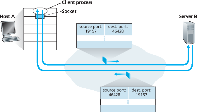
图 3.4 源端口号和目的端口号的反转
特别地,与 UDP 不同的是,两个具有不同源 IP 地址或源端口号的 TCP 报文段(除了用于建立连接的初始 TCP 报文段外)将被定向到两个不同的套接字。为了更深入地理解这一点,让我们重新考虑 第 2.7.2 节 中的 TCP 客户端-服务器编程示例:
TCP 服务器应用程序具有一个“欢迎套接字(welcoming socket)”,在端口号 12000 上等待来自 TCP 客户端的连接建立请求(见 图 2.29)。
TCP 客户端创建一个套接字并发送连接建立请求报文段,其代码如下:
clientSocket = socket(AF_INET, SOCK_STREAM)
clientSocket.connect((serverName,12000))
一个连接建立请求本质上就是一个 TCP 报文段,该报文段具有目的端口号 12000,并在 TCP 首部中设置了一个特殊的连接建立比特(将在 第 3.5 节 中讨论)。该报文段还包含一个由客户端选择的源端口号。
当运行服务器进程的主机操作系统收到目的端口为 12000 的传入连接请求报文段时,它会定位到正在端口号 12000 上等待连接的服务器进程。该服务器进程随后创建一个新套接字:
connectionSocket, addr = serverSocket.accept()
同时,服务器端的传输层记录该连接请求报文段中的以下四个值:(1) 报文段中的源端口号,(2) 源主机的 IP 地址,(3) 报文段中的目的端口号,以及 (4) 自己的 IP 地址。新创建的连接套接字由这四个值标识;所有随后到达的报文段,其源端口、源 IP 地址、目的端口和目的 IP 地址与这四个值匹配的,将被解复用到这个套接字。TCP 连接一旦建立,客户端和服务器就可以互相发送数据了。
服务器主机可能支持多个并发的 TCP 连接套接字,每个套接字绑定到一个进程,并且每个套接字由其独有的四元组标识。当 TCP 报文段到达主机时,将使用所有四个字段(源 IP 地址、源端口号、目的 IP 地址、目的端口号)将该报文段定向(解复用)到适当的套接字。
聚焦安全(FOCUS ON SECURITY)
端口扫描
我们已经看到,服务器进程会在一个开放端口上耐心等待远程客户端的连接。一些端口是为知名应用程序保留的(例如 Web、FTP、DNS 和 SMTP 服务器);其他端口则被流行应用程序按惯例使用(例如 Microsoft 2000 SQL 服务器监听 UDP 端口 1434)。因此,如果我们发现某个主机上的某个端口是开放的,就有可能将该端口映射到主机上运行的某个特定应用程序。这对系统管理员非常有用,他们经常希望了解网络中哪些主机正在运行哪些网络应用程序。但攻击者为了“侦察环境”,也同样希望知道目标主机上哪些端口是开放的。如果发现某个主机运行的应用程序存在已知的安全漏洞(例如,监听在端口 1434 上的 SQL 服务器曾存在缓冲区溢出漏洞,使远程用户可以在易受攻击主机上执行任意代码,该漏洞被 Slammer 蠕虫所利用 [CERT 2003–04]),那么该主机就容易遭到攻击。
确定哪些应用程序监听哪些端口是一个相对容易的任务。实际上有许多公共领域的程序称为端口扫描器,专门用于此目的。其中最常用的可能是 nmap,它可以从 http://nmap.org 免费获取,并包含在大多数 Linux 发行版中。对于 TCP,nmap 顺序扫描端口,查找接受 TCP 连接的端口;对于 UDP,nmap 也顺序扫描端口,查找响应所发送 UDP 报文段的端口。在这两种情况下,nmap 都会返回开放、关闭或不可达的端口列表。运行 nmap 的主机可以尝试扫描互联网上 任何地方 的目标主机。我们将在 第 3.5.6 节 中再次讨论 nmap,届时我们将探讨 TCP 连接管理。
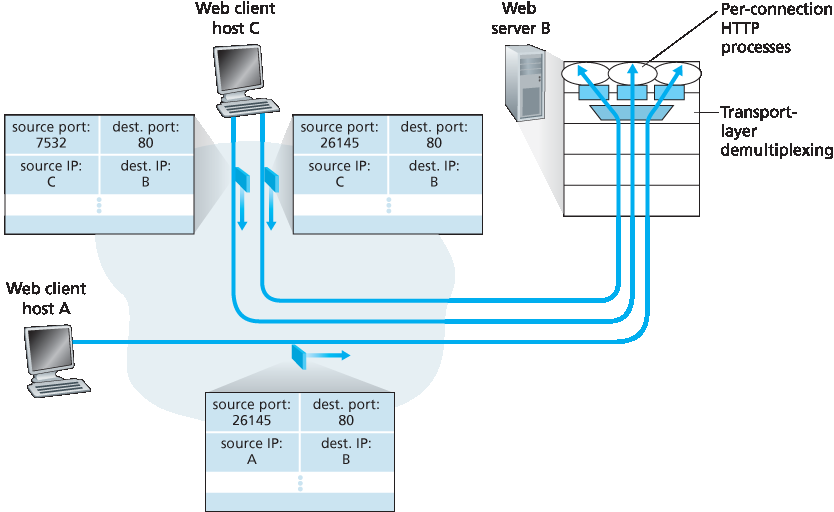
图 3.5 两个客户端使用相同的目的端口号(80)与同一个 Web 服务器通信
图 3.5 展示了这一情形,其中主机 C 向服务器 B 发起了两个 HTTP 会话,而主机 A 向 B 发起了一个 HTTP 会话。主机 A、C 和服务器 B 分别拥有各自唯一的 IP 地址。主机 C 为其两个 HTTP 连接分配了两个不同的源端口号(26145 和 7532)。由于主机 A 是独立于主机 C 分配源端口号的,它也可能为其 HTTP 连接分配源端口号 26145。但这并不是问题——服务器 B 依然能够正确地将这两个具有相同源端口号的连接解复用开,因为这两个连接具有不同的源 IP 地址。
In order to understand TCP demultiplexing, we have to take a close look at TCP sockets and TCP connection establishment. One subtle difference between a TCP socket and a UDP socket is that a TCP socket is identified by a four-tuple: (source IP address, source port number, destination IP address, destination port number). Thus, when a TCP segment arrives from the network to a host, the host uses all four values to direct (demultiplex) the segment to the appropriate socket.
Figure 3.4 The inversion of source and destination port numbers
In particular, and in contrast with UDP, two arriving TCP segments with different source IP addresses or source port numbers will (with the exception of a TCP segment carrying the original connection- establishment request) be directed to two different sockets. To gain further insight, let’s reconsider the TCP client-server programming example in Section 2.7.2:
The TCP server application has a “welcoming socket,” that waits for connection-establishment requests from TCP clients (see Figure 2.29) on port number 12000.
The TCP client creates a socket and sends a connection establishment request segment with the lines:
clientSocket = socket(AF_INET, SOCK_STREAM)
clientSocket.connect((serverName,12000))
A connection-establishment request is nothing more than a TCP segment with destination port number 12000 and a special connection-establishment bit set in the TCP header (discussed in Section 3.5). The segment also includes a source port number that was chosen by the client.
When the host operating system of the computer running the server process receives the incoming connection-request segment with destination port 12000, it locates the server process that is waiting to accept a connection on port number 12000. The server process then creates a new socket:
connectionSocket, addr = serverSocket.accept()
Also, the transport layer at the server notes the following four values in the connection-request segment: (1) the source port number in the segment, (2) the IP address of the source host, (3) the destination port number in the segment, and (4) its own IP address. The newly created connection socket is identified by these four values; all subsequently arriving segments whose source port, source IP address, destination port, and destination IP address match these four values will be demultiplexed to this socket. With the TCP connection now in place, the client and server can now send data to each other.
The server host may support many simultaneous TCP connection sockets, with each socket attached to a process, and with each socket identified by its own four-tuple. When a TCP segment arrives at the host, all four fields (source IP address, source port, destination IP address, destination port) are used to direct (demultiplex) the segment to the appropriate socket.
FOCUS ON SECURITY
Port Scanning
We’ve seen that a server process waits patiently on an open port for contact by a remote client. Some ports are reserved for well-known applications (e.g., Web, FTP, DNS, and SMTP servers); other ports are used by convention by popular applications (e.g., the Microsoft 2000 SQL server listens for requests on UDP port 1434). Thus, if we determine that a port is open on a host, we may be able to map that port to a specific application running on the host. This is very useful for system administrators, who are often interested in knowing which network applications are running on the hosts in their networks. But attackers, in order to “case the joint,” also want to know which ports are open on target hosts. If a host is found to be running an application with a known security flaw (e.g., a SQL server listening on port 1434 was subject to a buffer overflow, allowing a remote user to execute arbitrary code on the vulnerable host, a flaw exploited by the Slammer worm [CERT 2003–04]), then that host is ripe for attack.
Determining which applications are listening on which ports is a relatively easy task. Indeed there are a number of public domain programs, called port scanners, that do just that. Perhaps the most widely used of these is nmap, freely available at http://nmap.org and included in most Linux distributions. For TCP, nmap sequentially scans ports, looking for ports that are accepting TCP connections. For UDP, nmap again sequentially scans ports, looking for UDP ports that respond to transmitted UDP segments. In both cases, nmap returns a list of open, closed, or unreachable ports. A host running nmap can attempt to scan any target host anywhere in the Internet. We’ll revisit nmap in Section 3.5.6, when we discuss TCP connection management.
Figure 3.5 Two clients, using the same destination port number (80) to communicate with the same Web server application
The situation is illustrated in Figure 3.5, in which Host C initiates two HTTP sessions to server B, and Host A initiates one HTTP session to B. Hosts A and C and server B each have their own unique IP address—A, C, and B, respectively. Host C assigns two different source port numbers (26145 and 7532) to its two HTTP connections. Because Host A is choosing source port numbers independently of C, it might also assign a source port of 26145 to its HTTP connection. But this is not a problem—server B will still be able to correctly demultiplex the two connections having the same source port number, since the two connections have different source IP addresses.
Web 服务器与 TCP#
Web Servers and TCP
在结束本节讨论之前,有必要进一步谈谈 Web 服务器及其如何使用端口号。考虑一个主机在端口 80 上运行 Web 服务器(例如 Apache Web 服务器)。当客户端(例如浏览器)向服务器发送报文段时,所有报文段都将具有目的端口号 80。特别地,初始连接建立报文段以及承载 HTTP 请求消息的报文段都将具有目的端口号 80。如我们刚才描述的,服务器使用源 IP 地址和源端口号来区分来自不同客户端的报文段。
图 3.5 展示了一个 Web 服务器为每个连接生成一个新进程。如 图 3.5 所示,每个进程都有自己的连接套接字,用于接收 HTTP 请求并发送 HTTP 响应。不过我们需要说明,连接套接字与进程之间并不总是一一对应。实际上,现代高性能 Web 服务器通常仅使用一个进程,并为每个新的客户端连接创建一个具有新连接套接字的新线程。(线程可以看作是轻量级子进程。)如果你完成了 第 2 章 中的第一个编程作业,你就构建了一个采用该方式的 Web 服务器。对于这种服务器,任意时刻都可能存在多个连接套接字(具有不同标识符)绑定到同一个进程上。
如果客户端和服务器使用的是持久 HTTP,那么在整个持久连接期间,客户端和服务器将通过同一个服务器套接字交换 HTTP 消息。然而,如果客户端和服务器使用非持久 HTTP,那么每个请求/响应对都会创建并关闭一个新的 TCP 连接,因此每个请求/响应也会创建并关闭一个新的套接字。这种频繁的套接字创建和关闭会严重影响繁忙 Web 服务器的性能(尽管可以使用若干操作系统技巧来缓解该问题)。感兴趣的读者可参考 [ Nielsen 1997;Nahum 2002] 进一步了解持久与非持久 HTTP 背后的操作系统问题。
现在我们已讨论了传输层的复用与解复用,让我们继续讨论互联网中的一个传输协议 —— UDP。在下一节中,我们将看到 UDP 相对于网络层协议只增加了复用/解复用服务。
Before closing this discussion, it’s instructive to say a few additional words about Web servers and how they use port numbers. Consider a host running a Web server, such as an Apache Web server, on port 80. When clients (for example, browsers) send segments to the server, all segments will have destination port 80. In particular, both the initial connection-establishment segments and the segments carrying HTTP request messages will have destination port 80. As we have just described, the server distinguishes the segments from the different clients using source IP addresses and source port numbers.
Figure 3.5 shows a Web server that spawns a new process for each connection. As shown in Figure 3.5, each of these processes has its own connection socket through which HTTP requests arrive and HTTP responses are sent. We mention, however, that there is not always a one-to-one correspondence between connection sockets and processes. In fact, today’s high-performing Web servers often use only one process, and create a new thread with a new connection socket for each new client connection. (A thread can be viewed as a lightweight subprocess.) If you did the first programming assignment in Chapter 2, you built a Web server that does just this. For such a server, at any given time there may be many connection sockets (with different identifiers) attached to the same process.
If the client and server are using persistent HTTP, then throughout the duration of the persistent connection the client and server exchange HTTP messages via the same server socket. However, if the client and server use non-persistent HTTP, then a new TCP connection is created and closed for every request/response, and hence a new socket is created and later closed for every request/response. This frequent creating and closing of sockets can severely impact the performance of a busy Web server (although a number of operating system tricks can be used to mitigate the problem). Readers interested in the operating system issues surrounding persistent and non-persistent HTTP are encouraged to see [ Nielsen 1997; Nahum 2002].
Now that we’ve discussed transport-layer multiplexing and demultiplexing, let’s move on and discuss one of the Internet’s transport protocols, UDP. In the next section we’ll see that UDP adds little more to the network-layer protocol than a multiplexing/demultiplexing service.