6.6 数据中心网络#
6.6 Data Center Networking
近年来,互联网公司如 Google、Microsoft、Facebook 和 Amazon(以及它们在亚洲和欧洲的对应公司)构建了大规模的数据中心,每个数据中心容纳数万到数十万台主机,同时支持多种不同的云应用(如搜索、电子邮件、社交网络和电子商务)。每个数据中心拥有自己的数据中心网络,用以连接其内部主机并将数据中心连接到互联网。在本节中,我们将简要介绍面向云应用的 数据中心网络。
一个大型数据中心的成本非常高,对于一个拥有 100,000 台主机的数据中心来说,每月成本超过 1200 万美元 [Greenberg 2009a]。在这些成本中,大约 45% 可归因于主机本身(每 3–4 年需要更换一次);25% 用于基础设施,包括变压器、不间断电源(UPS)系统、长时间断电时的发电机以及冷却系统;15% 为电力成本;15% 为网络相关成本,包括网络设备(交换机、路由器和负载均衡器)、外部链路和中转流量成本。(在这些百分比中,设备成本是按摊销计算的,以便对一次性采购和持续性开销(如电力)使用统一的成本指标。)虽然网络并不是最大的成本项,但网络创新是降低整体成本并最大化性能的关键 [Greenberg 2009a]。
数据中心中的“工蜂”是主机:它们提供内容(如网页和视频),存储电子邮件和文档,并集体执行大规模分布式计算(如搜索引擎的分布式索引计算)。数据中心中的主机称为 刀片(blades),外形类似披萨盒,通常为包含 CPU、内存和磁盘存储的商用主机。这些主机被堆叠在机架中,每个机架通常拥有 20 到 40 个刀片。在每个机架顶部有一个交换机,称为 Top of Rack(TOR)交换机,用于连接机架内主机及连接数据中心中其他交换机。具体而言,机架中的每台主机都通过网络接口卡连接到其 TOR 交换机,每个 TOR 交换机还有额外的端口可用于连接其他交换机。如今,主机通常通过 40 Gbps 的以太网连接到其 TOR 交换机 [Greenberg 2015]。每台主机还被分配一个数据中心内部的 IP 地址。
数据中心网络支持两种类型的流量:外部客户端与内部主机之间的流量,以及内部主机之间的流量。为了处理外部客户端与内部主机之间的流量,数据中心网络包括一个或多个 边界路由器,将数据中心网络连接到公共互联网。因此,数据中心网络既互连各个机架,又将机架连接到边界路由器。图 6.30 展示了一个数据中心网络的示例。数据中心网络设计,即设计用于连接各个机架和边界路由器的互联网络及协议的技术,近年来已成为计算机网络研究的重要分支 [Al-Fares 2008; Greenberg 2009a; Greenberg 2009b; Mysore 2009; Guo 2009; Wang 2010]。
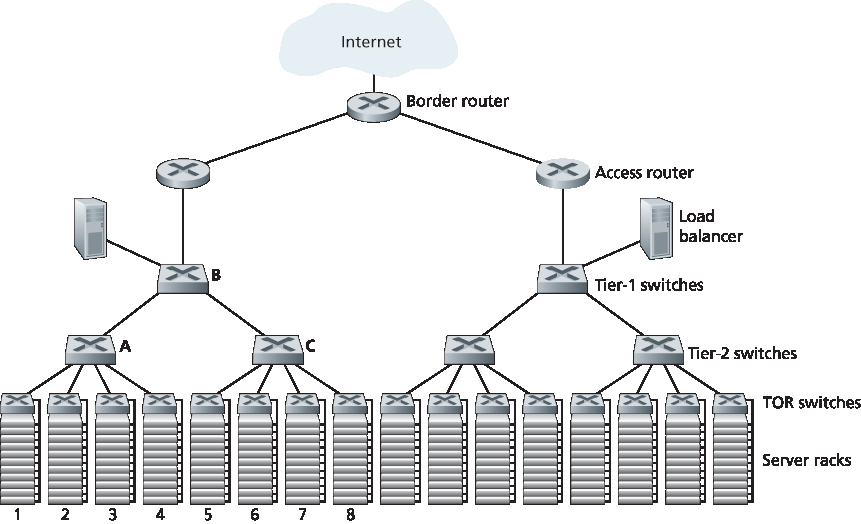
图 6.30 一种具有分层拓扑结构的数据中心网络
In recent years, Internet companies such as Google, Microsoft, Facebook, and Amazon (as well as their counterparts in Asia and Europe) have built massive data centers, each housing tens to hundreds of thousands of hosts, and concurrently supporting many distinct cloud applications (e.g., search, e-mail, social networking, and e-commerce). Each data center has its own data center network that interconnects its hosts with each other and interconnects the data center with the Internet. In this section, we provide a brief introduction to data center networking for cloud applications.
The cost of a large data center is huge, exceeding $12 million per month for a 100,000 host data center [Greenberg 2009a]. Of these costs, about 45 percent can be attributed to the hosts themselves (which need to be replaced every 3–4 years); 25 percent to infrastructure, including transformers, uninterruptable power supplies (UPS) systems, generators for long-term outages, and cooling systems; 15 percent for electric utility costs for the power draw; and 15 percent for networking, including network gear (switches, routers and load balancers), external links, and transit traffic costs. (In these percentages, costs for equipment are amortized so that a common cost metric is applied for one-time purchases and ongoing expenses such as power.) While networking is not the largest cost, networking innovation is the key to reducing overall cost and maximizing performance [Greenberg 2009a].
The worker bees in a data center are the hosts: They serve content (e.g., Web pages and videos), store e-mails and documents, and collectively perform massively distributed computations (e.g., distributed index computations for search engines). The hosts in data centers, called blades and resembling pizza boxes, are generally commodity hosts that include CPU, memory, and disk storage. The hosts are stacked in racks, with each rack typically having 20 to 40 blades. At the top of each rack there is a switch, aptly named the Top of Rack (TOR) switch, that interconnects the hosts in the rack with each other and with other switches in the data center. Specifically, each host in the rack has a network interface card that connects to its TOR switch, and each TOR switch has additional ports that can be connected to other switches. Today hosts typically have 40 Gbps Ethernet connections to their TOR switches [Greenberg 2015]. Each host is also assigned its own data-center-internal IP address.
The data center network supports two types of traffic: traffic flowing between external clients and internal hosts and traffic flowing between internal hosts. To handle flows between external clients and internal hosts, the data center network includes one or more border routers, connecting the data center network to the public Internet. The data center network therefore interconnects the racks with each other and connects the racks to the border routers. Figure 6.30 shows an example of a data center network. Data center network design, the art of designing the interconnection network and protocols that connect the racks with each other and with the border routers, has become an important branch of computer networking research in recent years [Al-Fares 2008; Greenberg 2009a; Greenberg 2009b; Mysore 2009; Guo 2009; Wang 2010].
Figure 6.30 A data center network with a hierarchical topology
负载均衡#
Load Balancing
像 Google 或 Microsoft 这样的云数据中心可同时提供多种应用,如搜索、电子邮件和视频应用。为了支持来自外部客户端的请求,每个应用都关联有一个公共可见的 IP 地址,客户端将请求发送到该地址,并从中接收响应。在数据中心内部,外部请求首先被定向到一个 负载均衡器,该负载均衡器负责将请求分发给主机,根据其当前负载在主机之间实现负载均衡。一个大型数据中心通常有多个负载均衡器,每个负责一组特定的云应用。这类负载均衡器有时被称为“第 4 层交换机”,因为它基于分组中的目标端口号(第 4 层)以及目标 IP 地址做出决策。当负载均衡器接收到某个特定应用的请求时,它会将该请求转发给处理该应用的某个主机。(主机随后可能会调用其他主机的服务来协助处理请求。)当主机完成请求处理后,会将响应发送回负载均衡器,后者再将响应转发给外部客户端。负载均衡器不仅在主机之间均衡负载,还提供类似 NAT 的功能,将公共外部 IP 地址转换为适当主机的内部 IP 地址,反向方向的分组也执行相应转换。这一机制防止了客户端直接与主机联系,具有隐藏内部网络结构和防止客户端直接访问主机的安全优势。
A cloud data center, such as a Google or Microsoft data center, provides many applications concurrently, such as search, e-mail, and video applications. To support requests from external clients, each application is associated with a publicly visible IP address to which clients send their requests and from which they receive responses. Inside the data center, the external requests are first directed to a load balancer whose job it is to distribute requests to the hosts, balancing the load across the hosts as a function of their current load. A large data center will often have several load balancers, each one devoted to a set of specific cloud applications. Such a load balancer is sometimes referred to as a “layer-4 switch” since it makes decisions based on the destination port number (layer 4) as well as destination IP address in the packet. Upon receiving a request for a particular application, the load balancer forwards it to one of the hosts that handles the application. (A host may then invoke the services of other hosts to help process the request.) When the host finishes processing the request, it sends its response back to the load balancer, which in turn relays the response back to the external client. The load balancer not only balances the work load across hosts, but also provides a NAT-like function, translating the public external IP address to the internal IP address of the appropriate host, and then translating back for packets traveling in the reverse direction back to the clients. This prevents clients from contacting hosts directly, which has the security benefit of hiding the internal network structure and preventing clients from directly interacting with the hosts.
分层架构#
Hierarchical Architecture
对于仅容纳几千台主机的小型数据中心,由边界路由器、负载均衡器以及通过单个以太网交换机互连的几十个机架组成的简单网络可能就足够了。但为了扩展到数万乃至数十万台主机,数据中心通常采用如 图 6.30 所示的 路由器和交换机的分层结构。在分层结构的顶部,边界路由器连接到接入路由器(图 6.30 仅展示两个,但实际上可能有更多)。每个接入路由器下有三层交换机。每个接入路由器连接到一个顶层交换机,每个顶层交换机连接多个第二层交换机和一个负载均衡器。每个第二层交换机又通过 TOR(第三层交换机)连接多个机架。所有链路通常使用以太网协议作为链路层和物理层协议,混合使用铜缆和光纤。采用这种分层设计,可以将数据中心扩展到数十万台主机。
由于云应用提供商持续提供高可用应用至关重要,数据中心还包括冗余的网络设备和冗余链路设计(图 6.30 中未显示)。例如,每个 TOR 交换机可以连接到两个第二层交换机,每个接入路由器、第一层交换机和第二层交换机都可以复制并集成到设计中 [Cisco 2012; Greenberg 2009b]。在 图 6.30 的分层设计中,注意到每个接入路由器下的主机构成一个子网。为了限制 ARP 广播流量,每个这样的子网被进一步划分为包含几百台主机的 VLAN 子网 [Greenberg 2009a]。
尽管上述传统分层架构解决了可扩展性问题,但它存在主机到主机通信能力受限的问题 [Greenberg 2009b]。为了解这一限制,再次参考 图 6.30,假设每台主机通过 1 Gbps 链路连接到 TOR 交换机,而交换机之间的链路为 10 Gbps。处于同一机架的两个主机总是可以以 1 Gbps 全速通信,唯一限制来自主机的网络接口卡。但如果数据中心网络中存在大量同时的流,那么两个不同机架的主机之间的最大通信速率可能会大幅下降。为说明此问题,考虑包含 40 对来自不同机架主机之间的 40 个同时流的流量模式。具体而言,假设 图 6.30 中机架 1 中的 10 台主机分别向机架 5 中对应的 10 台主机发送流;类似地,机架 2 与 6、机架 3 与 7、机架 4 与 8 各有 10 个流。如果每个流在通过链路时平均分配链路容量,则通过 A 到 B 链路(以及 B 到 C 链路)的 40 个流将各自仅获得 10 Gbps / 40 = 250 Mbps 的带宽,这远低于主机网卡的 1 Gbps 速率。对于需要穿越更高层的流而言,问题将更加严重。一种解决方案是部署更高速率的交换机和路由器。但这将显著增加数据中心成本,因为高速率端口的交换机和路由器价格非常昂贵。
支持高带宽主机到主机通信很重要,因为数据中心的一个关键要求是计算和服务的部署灵活性 [Greenberg 2009b; Farrington 2010]。例如,大规模互联网搜索引擎可能在分布于多个机架的数千台主机上运行,主机间带宽需求很大。同样,像 EC2 这样的云计算服务可能希望将组成客户服务的多个虚拟机部署在数据中心内任意位置容量最足的物理主机上。如果这些主机分布在多个机架中,上述网络瓶颈可能导致性能不佳。
For a small data center housing only a few thousand hosts, a simple network consisting of a border router, a load balancer, and a few tens of racks all interconnected by a single Ethernet switch could possibly suffice. But to scale to tens to hundreds of thousands of hosts, a data center often employs a hierarchy of routers and switches, such as the topology shown in Figure 6.30. At the top of the hierarchy, the border router connects to access routers (only two are shown in Figure 6.30, but there can be many more). Below each access router there are three tiers of switches. Each access router connects to a top-tier switch, and each top-tier switch connects to multiple second-tier switches and a load balancer. Each second-tier switch in turn connects to multiple racks via the racks’ TOR switches (third-tier switches). All links typically use Ethernet for their link-layer and physical-layer protocols, with a mix of copper and fiber cabling. With such a hierarchical design, it is possible to scale a data center to hundreds of thousands of hosts.
Because it is critical for a cloud application provider to continually provide applications with high availability, data centers also include redundant network equipment and redundant links in their designs (not shown in Figure 6.30). For example, each TOR switch can connect to two tier-2 switches, and each access router, tier-1 switch, and tier-2 switch can be duplicated and integrated into the design [Cisco 2012; Greenberg 2009b]. In the hierarchical design in Figure 6.30, observe that the hosts below each access router form a single subnet. In order to localize ARP broadcast traffic, each of these subnets is further partitioned into smaller VLAN subnets, each comprising a few hundred hosts [Greenberg 2009a].
Although the conventional hierarchical architecture just described solves the problem of scale, it suffers from limited host-to-host capacity [Greenberg 2009b]. To understand this limitation, consider again Figure 6.30, and suppose each host connects to its TOR switch with a 1 Gbps link, whereas the links between switches are 10 Gbps Ethernet links. Two hosts in the same rack can always communicate at a full 1 Gbps, limited only by the rate of the hosts’ network interface cards. However, if there are many simultaneous flows in the data center network, the maximum rate between two hosts in different racks can be much less. To gain insight into this issue, consider a traffic pattern consisting of 40 simultaneous flows between 40 pairs of hosts in different racks. Specifically, suppose each of 10 hosts in rack 1 in Figure 6.30 sends a flow to a corresponding host in rack 5. Similarly, there are ten simultaneous flows between pairs of hosts in racks 2 and 6, ten simultaneous flows between racks 3 and 7, and ten simultaneous flows between racks 4 and 8. If each flow evenly shares a link’s capacity with other flows traversing that link, then the 40 flows crossing the 10 Gbps A-to-B link (as well as the 10 Gbps B-to-C link) will each only receive 10 Gbps/40=250 Mbps, which is significantly less than the 1 Gbps network interface card rate. The problem becomes even more acute for flows between hosts that need to travel higher up the hierarchy. One possible solution to this limitation is to deploy higher-rate switches and routers. But this would significantly increase the cost of the data center, because switches and routers with high port speeds are very expensive.
Supporting high-bandwidth host-to-host communication is important because a key requirement in data centers is flexibility in placement of computation and services [Greenberg 2009b; Farrington 2010]. For example, a large-scale Internet search engine may run on thousands of hosts spread across multiple racks with significant bandwidth requirements between all pairs of hosts. Similarly, a cloud computing service such as EC2 may wish to place the multiple virtual machines comprising a customer’s service on the physical hosts with the most capacity irrespective of their location in the data center. If these physical hosts are spread across multiple racks, network bottlenecks as described above may result in poor performance.
数据中心网络的发展趋势#
Trends in Data Center Networking
为了降低数据中心成本,同时提升其延迟和吞吐性能,Google、Facebook、Amazon 和 Microsoft 等互联网云巨头不断部署新的数据中心网络设计。尽管这些设计是专有的,但仍能识别出许多重要的发展趋势。
其中一个趋势是部署新的互联架构和网络协议,以克服传统分层设计的缺点。一种做法是使用 全互联拓扑 替代交换机和路由器的分层结构 [Facebook 2014; Al-Fares 2008; Greenberg 2009b; Guo 2009],如 图 6.31 所示。在该设计中,每个第一层交换机连接到所有的第二层交换机,以便(1)主机间通信无需跨越交换层级;(2)在有 n 个第一层交换机的情况下,任意两个第二层交换机之间存在 n 条不相交路径。这种设计可显著提升主机到主机容量。仍以 40 个流的示例为例,图 6.31 中的拓扑可以处理这种流量模式,因为在第一个和第二个第二层交换机之间存在四条路径,合计提供 40 Gbps 的总带宽。这种设计不仅缓解了主机间通信容量限制,还创建了一个更灵活的计算与服务环境,使得不连接到同一交换机的任意两个机架间通信在逻辑上等效,无论其在数据中心中的位置如何。
另一个主要趋势是采用基于集装箱的模块化数据中心(MDC) [YouTube 2009; Waldrop 2007]。在 MDC 中,工厂在一个标准 12 米集装箱内建造一个“迷你数据中心”,并将该集装箱运送至数据中心位置。每个集装箱最多可容纳几千台主机,这些主机密集堆叠在数十个机架中。在数据中心现场,多个集装箱彼此互联并连接到互联网。一旦预制集装箱部署到数据中心,通常很难维护。因此,每个集装箱设计为可优雅降级:随着组件(服务器和交换机)逐渐失效,集装箱继续运行但性能下降。当多个组件失效并导致性能低于阈值时,该集装箱将被整体更换。
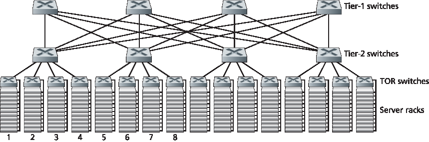
图 6.31 高度互联的数据中心网络拓扑
用集装箱构建数据中心带来了新的网络挑战。使用 MDC 时存在两类网络:集装箱内部网络以及连接各集装箱的核心网络 [Guo 2009; Farrington 2010]。在每个集装箱内部,规模达到几千台主机,可以使用廉价商用千兆以太网交换机构建全互联网络(如上所述)。然而,核心网络的设计,即在数百到数千个集装箱之间提供高主机间带宽,仍是一个挑战性问题。文献 [Farrington 2010] 提出了用于互联集装箱的电/光混合交换架构。
使用高度互联拓扑时,一个主要问题是设计交换机间的路由算法。一种可能性 [Greenberg 2009b] 是使用某种形式的随机路由。另一种可能性 [Guo 2009] 是在每个主机上部署多个网络接口卡,将其连接到多个廉价交换机上,并允许主机本身智能地在交换机间路由流量。这些方法的变体和扩展目前正被部署到现代数据中心中。
另一个重要趋势是大型云服务提供商越来越多地自建或定制数据中心中的几乎所有组件,包括网络适配器、交换机、路由器、TOR、软件和网络协议 [Greenberg 2015, Singh 2015]。Amazon 首创的另一个趋势是通过“可用区(availability zones)”提升可靠性,本质上是在附近的不同建筑中复制独立的数据中心。通过让建筑彼此靠近(相距数公里),可以在同一可用区内同步事务性数据,同时提供容错能力 [Amazon 2014]。未来还将不断涌现更多关于数据中心设计的创新;感兴趣的读者可以查阅最新的关于数据中心网络设计的论文和视频。
In order to reduce the cost of data centers, and at the same time improve their delay and throughput performance, Internet cloud giants such as Google, Facebook, Amazon, and Microsoft are continually deploying new data center network designs. Although these designs are proprietary, many important trends can nevertheless be identified.
One such trend is to deploy new interconnection architectures and network protocols that overcome the drawbacks of the traditional hierarchical designs. One such approach is to replace the hierarchy of switches and routers with a fully connected topology [Facebook 2014; Al-Fares 2008; Greenberg 2009b; Guo 2009], such as the topology shown in Figure 6.31. In this design, each tier-1 switch connects to all of the tier-2 switches so that (1) host-to-host traffic never has to rise above the switch tiers, and (2) with n tier-1 switches, between any two tier-2 switches there are n disjoint paths. Such a design can significantly improve the host-to-host capacity. To see this, consider again our example of 40 flows. The topology in Figure 6.31 can handle such a flow pattern since there are four distinct paths between the first tier-2 switch and the second tier-2 switch, together providing an aggregate capacity of 40 Gbps between the first two tier-2 switches. Such a design not only alleviates the host-to-host capacity limitation, but also creates a more flexible computation and service environment in which communication between any two racks not connected to the same switch is logically equivalent, irrespective of their locations in the data center.
Another major trend is to employ shipping container–based modular data centers (MDCs) [YouTube 2009; Waldrop 2007]. In an MDC, a factory builds, within a standard 12-meter shipping container, a “mini data center” and ships the container to the data center location. Each container has up to a few thousand hosts, stacked in tens of racks, which are packed closely together. At the data center location, multiple containers are interconnected with each other and also with the Internet. Once a prefabricated container is deployed at a data center, it is often difficult to service. Thus, each container is designed for graceful performance degradation: as components (servers and switches) fail over time, the container continues to operate but with degraded performance. When many components have failed and performance has dropped below a threshold, the entire container is removed and replaced with a fresh one.
Figure 6.31 Highly interconnected data network topology
Building a data center out of containers creates new networking challenges. With an MDC, there are two types of networks: the container-internal networks within each of the containers and the core network connecting each container [Guo 2009; Farrington 2010]. Within each container, at the scale of up to a few thousand hosts, it is possible to build a fully connected network (as described above) using inexpensive commodity Gigabit Ethernet switches. However, the design of the core network, interconnecting hundreds to thousands of containers while providing high host-to-host bandwidth across containers for typical workloads, remains a challenging problem. A hybrid electrical/optical switch architecture for interconnecting the containers is proposed in [Farrington 2010].
When using highly interconnected topologies, one of the major issues is designing routing algorithms among the switches. One possibility [Greenberg 2009b] is to use a form of random routing. Another possibility [Guo 2009] is to deploy multiple network interface cards in each host, connect each host to multiple low-cost commodity switches, and allow the hosts themselves to intelligently route traffic among the switches. Variations and extensions of these approaches are currently being deployed in contemporary data centers.
Another important trend is that large cloud providers are increasingly building or customizing just about everything that is in their data centers, including network adapters, switches routers, TORs, software, and networking protocols [Greenberg 2015, Singh 2015]. Another trend, pioneered by Amazon, is to improve reliability with “availability zones,” which essentially replicate distinct data centers in different nearby buildings. By having the buildings nearby (a few kilometers apart), transactional data can be synchronized across the data centers in the same availability zone while providing fault tolerance [Amazon 2014]. Many more innovations in data center design are likely to continue to come; interested readers are encouraged to see the recent papers and videos on data center network design.