3.5 面向连接的传输:TCP#
3.5 Connection-Oriented Transport: TCP
既然我们已经介绍了可靠数据传输的基本原理,现在让我们来看看 TCP—— 互联网的传输层面向连接的可靠传输协议。本节中,我们将看到为了提供可靠的数据传输,TCP 依赖于前面章节讨论的许多基本原理,包括错误检测、重传、累积确认、定时器,以及序列号和确认号的报头字段。TCP 的定义见 RFC 793、 RFC 1122、 RFC 1323、 RFC 2018 和 RFC 2581。
Now that we have covered the underlying principles of reliable data transfer, let’s turn to TCP—the Internet’s transport-layer, connection-oriented, reliable transport protocol. In this section, we’ll see that in order to provide reliable data transfer, TCP relies on many of the underlying principles discussed in the previous section, including error detection, retransmissions, cumulative acknowledgments, timers, and header fields for sequence and acknowledgment numbers. TCP is defined in RFC 793, RFC 1122, RFC 1323, RFC 2018, and RFC 2581.
3.5.1 TCP 连接#
3.5.1 The TCP Connection
TCP 被称为 面向连接,因为在一个应用进程开始向另一个应用进程发送数据之前,这两个进程必须先相互“握手”——也就是说,它们必须先相互发送一些初始报文段,以建立后续数据传输的参数。作为 TCP 连接建立的一部分,连接的双方都会初始化许多 TCP 状态变量(其中许多将在本节和 第3.7节 中讨论),这些状态变量与 TCP 连接相关联。
TCP“连接”并不是电路交换网络中端到端的时分多路复用(TDM)或频分多路复用(FDM)电路。相反,“连接”是逻辑上的,公共状态仅存在于两个通信端系统中的 TCP 中。回想一下,TCP 协议只在端系统中运行,而不在中间网络设备(路由器和链路层交换机)中运行,因此中间网络设备不维护 TCP 连接状态。事实上,中间路由器对 TCP 连接完全不了解;它们只看到数据报,而不是连接。
TCP 连接提供 全双工服务:如果主机 A 上的进程 A 与主机 B 上的进程 B 之间存在 TCP 连接,那么应用层数据可以同时从进程 A 流向进程 B,同时也可以从进程 B 流向进程 A。TCP 连接总是 点对点 的,也就是说,连接是在单个发送方和单个接收方之间建立的。所谓的“多播”(参见本书在线补充材料)——即一次发送操作将数据从一个发送方传输给多个接收方——在 TCP 中是不可能的。使用 TCP 时,两个主机是一对伙伴,三个就成了“人多嘴杂”了!
现在让我们看看 TCP 连接是如何建立的。假设一个主机上的进程想要与另一个主机上的进程建立连接。回想一下,发起连接的进程称为客户端进程,另一个进程称为服务器进程。客户端应用进程首先通知客户端传输层它想要建立与服务器进程的连接。回到第 2.7.2 节,一个 Python 客户端程序通过执行如下命令实现这一点:
clientSocket.connect((serverName, serverPort))
其中 serverName 是服务器名称, serverPort 标识服务器上的进程。然后客户端中的 TCP 继续与服务器中的 TCP 建立 TCP 连接。本节末尾我们将详细讨论连接建立过程。现在只需知道,客户端首先发送一个特殊的 TCP 报文段;服务器回应第二个特殊 TCP 报文段;最后客户端再回应第三个特殊报文段。前三个报文段中,前两个不携带负载(即没有应用层数据);第三个报文段可能携带负载。因为两主机之间发送了三个报文段,这个连接建立过程通常被称为 三次握手。
案例历史
Vinton Cerf、Robert Kahn 和 TCP/IP
1970 年代初,分组交换网络开始快速发展,ARPAnet——互联网的前身——只是众多网络之一。每个网络都有自己的协议。两位研究人员 Vinton Cerf 和 Robert Kahn 认识到互联这些网络的重要性,发明了一种跨网络协议,称为 TCP/IP,即传输控制协议/互联网协议。虽然 Cerf 和 Kahn 最初将该协议视为一个整体,后来它被拆分为两个部分,分别是 TCP 和 IP,它们各自独立运行。Cerf 和 Kahn 于 1974 年 5 月在 IEEE Transactions on Communications Technology 上发表了有关 TCP/IP 的论文 [Cerf 1974]。
如今互联网的核心协议 TCP/IP 诞生于个人电脑、工作站、智能手机和平板出现之前,诞生于以太网、有线和 DSL、WiFi 及其他接入网络技术普及之前,也早于万维网、社交媒体和视频流媒体。Cerf 和 Kahn 预见了需要一种网络协议,既能广泛支持未来未定义的应用,也能让任意主机和链路层协议实现互操作。
2004 年,Cerf 和 Kahn 获得 ACM 图灵奖,被誉为“计算机领域的诺贝尔奖”,以表彰他们在网络互联领域的开创性工作,包括设计和实现互联网基本通信协议 TCP/IP 以及在网络领域的卓越领导力。
一旦 TCP 连接建立,两个应用进程便可相互发送数据。让我们考虑从客户端进程向服务器进程发送数据。客户端进程通过套接字(进程的门)传递数据流,如 第2.7节 所述。一旦数据通过套接字传入,数据就交由客户端的 TCP 处理。如 图3.28 所示,TCP 将数据放入连接的 发送缓冲区,该缓冲区是在初始三次握手期间分配的缓冲区之一。TCP 会不时地从发送缓冲区中获取数据块,并将数据传递给网络层。有趣的是,TCP 规范 [RFC 793] 对 TCP 何时发送缓冲数据的规定非常宽松,指出 TCP 应该“在方便的时候发送这些数据段”。可以放入单个数据段的数据量上限由 最大报文段长度(MSS) 限制。MSS 通常先由本地主机可发送的最大链路层帧长度(即 最大传输单元 MTU )确定,然后设置 MSS 以保证 TCP 段(封装在 IP 数据报中)加上 TCP/IP 头部长度(通常为 40 字节)能装入单个链路层帧。以太网和 PPP 链路层协议的 MTU 为 1500 字节,因此 MSS 的典型值是 1460 字节。也有人提出根据路径 MTU(从源到目的地所有链路上可发送的最大链路层帧长度)动态发现路径 MTU,并基于路径 MTU 设置 MSS [RFC 1191]。需要注意的是,MSS 是指数据段中应用层数据的最大长度,而不是包括头部的 TCP 段的最大大小。(术语有些混淆,但已经沿用多年,只能接受。)
TCP 将客户端数据的每个数据块与 TCP 头部配对,形成 TCP 段 。这些段被下传到网络层,在那里被单独封装在网络层 IP 数据报内。IP 数据报随后被发送到网络中。当 TCP 在另一端接收到一个段时,段中的数据被放入 TCP 连接的接收缓冲区,如 图3.28 所示。应用程序从该缓冲区读取数据流。连接的双方各有自己的发送缓冲区和接收缓冲区。(你可以访问 http://www.awl.com/kurose-ross 观看在线流控动画,观察发送和接收缓冲区的工作情况。)
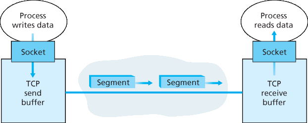
图3.28 TCP 发送和接收缓冲区
通过以上讨论,我们看到 TCP 连接由缓冲区、变量和连接到一台主机中进程的套接字组成,另一套缓冲区、变量和连接到另一台主机中进程的套接字组成。如前所述,主机之间的网络设备(路由器、交换机、中继器)不为连接分配任何缓冲区或变量。
TCP is said to be connection-oriented because before one application process can begin to send data to another, the two processes must first “handshake” with each other—that is, they must send some preliminary segments to each other to establish the parameters of the ensuing data transfer. As part of TCP connection establishment, both sides of the connection will initialize many TCP state variables (many of which will be discussed in this section and in Section 3.7) associated with the TCP connection.
The TCP “connection” is not an end-to-end TDM or FDM circuit as in a circuit-switched network. Instead, the “connection” is a logical one, with common state residing only in the TCPs in the two communicating end systems. Recall that because the TCP protocol runs only in the end systems and not in the intermediate network elements (routers and link-layer switches), the intermediate network elements do not maintain TCP connection state. In fact, the intermediate routers are completely oblivious to TCP connections; they see datagrams, not connections.
A TCP connection provides a full-duplex service: If there is a TCP connection between Process A on one host and Process B on another host, then application-layer data can flow from Process A to Process B at the same time as application-layer data flows from Process B to Process A. A TCP connection is also always point-to-point, that is, between a single sender and a single receiver. So- called “multicasting” (see the online supplementary materials for this text)—the transfer of data from one sender to many receivers in a single send operation—is not possible with TCP. With TCP, two hosts are company and three are a crowd!
Let’s now take a look at how a TCP connection is established. Suppose a process running in one host wants to initiate a connection with another process in another host. Recall that the process that is initiating the connection is called the client process, while the other process is called the server process. The client application process first informs the client transport layer that it wants to establish a connection to a process in the server. Recall from Section 2.7.2, a Python client program does this by issuing the command
clientSocket.connect((serverName, serverPort))
where serverName is the name of the server and serverPort identifies the process on the server. TCP in the client then proceeds to establish a TCP connection with TCP in the server. At the end of this section we discuss in some detail the connection-establishment procedure. For now it suffices to know that the client first sends a special TCP segment; the server responds with a second special TCP segment; and finally the client responds again with a third special segment. The first two segments carry no payload, that is, no application-layer data; the third of these segments may carry a payload. Becausethree segments are sent between the two hosts, this connection-establishment procedure is often referred to as a three-way handshake.
CASE HISTORY
Vinton Cerf, Robert Kahn, and TCP/IP
In the early 1970s, packet-switched networks began to proliferate, with the ARPAnet—the precursor of the Internet—being just one of many networks. Each of these networks had its own protocol. Two researchers, Vinton Cerf and Robert Kahn, recognized the importance of interconnecting these networks and invented a cross-network protocol called TCP/IP, which stands for Transmission Control Protocol/Internet Protocol. Although Cerf and Kahn began by seeing the protocol as a single entity, it was later split into its two parts, TCP and IP, which operated separately. Cerf and Kahn published a paper on TCP/IP in May 1974 in IEEE Transactions on Communications Technology [Cerf 1974].
The TCP/IP protocol, which is the bread and butter of today’s Internet, was devised before PCs, workstations, smartphones, and tablets, before the proliferation of Ethernet, cable, and DSL, WiFi, and other access network technologies, and before the Web, social media, and streaming video. Cerf and Kahn saw the need for a networking protocol that, on the one hand, provides broad support for yet-to-be-defined applications and, on the other hand, allows arbitrary hosts and link-layer protocols to interoperate.
In 2004, Cerf and Kahn received the ACM’s Turing Award, considered the “Nobel Prize of Computing” for “pioneering work on internetworking, including the design and implementation of the Internet’s basic communications protocols, TCP/IP, and for inspired leadership in networking.”
Once a TCP connection is established, the two application processes can send data to each other. Let’s consider the sending of data from the client process to the server process. The client process passes a stream of data through the socket (the door of the process), as described in Section 2.7. Once the data passes through the door, the data is in the hands of TCP running in the client. As shown in Figure 3.28, TCP directs this data to the connection’s send buffer, which is one of the buffers that is set aside during the initial three-way handshake. From time to time, TCP will grab chunks of data from the send buffer and pass the data to the network layer. Interestingly, the TCP specification [RFC 793] is very laid back about specifying when TCP should actually send buffered data, stating that TCP should “send that data in segments at its own convenience.” The maximum amount of data that can be grabbed and placed in a segment is limited by the maximum segment size (MSS). The MSS is typically set by first determining the length of the largest link-layer frame that can be sent by the local sending host (the so- called maximum transmission unit, MTU), and then setting the MSS to ensure that a TCP segment (when encapsulated in an IP datagram) plus the TCP/IP header length (typically 40 bytes) will fit into a single link-layer frame. Both Ethernet and PPP link-layer protocols have an MTU of 1,500 bytes. Thus a typical value of MSS is 1460 bytes. Approaches have also been proposed for discovering the path MTU —the largest link-layer frame that can be sent on all links from source to destination [RFC 1191] —and setting the MSS based on the path MTU value. Note that the MSS is the maximum amount of application-layer data in the segment, not the maximum size of the TCP segment including headers. (This terminology is confusing, but we have to live with it, as it is well entrenched.)
TCP pairs each chunk of client data with a TCP header, thereby forming TCP segments. The segments are passed down to the network layer, where they are separately encapsulated within network-layer IP datagrams. The IP datagrams are then sent into the network. When TCP receives a segment at the other end, the segment’s data is placed in the TCP connection’s receive buffer, as shown in Figure 3.28. The application reads the stream of data from this buffer. Each side of the connection has its own send buffer and its own receive buffer. (You can see the online flow-control applet at http://www.awl.com/kurose-ross, which provides an animation of the send and receive buffers.)
Figure 3.28 TCP send and receive buffers
We see from this discussion that a TCP connection consists of buffers, variables, and a socket connection to a process in one host, and another set of buffers, variables, and a socket connection to a process in another host. As mentioned earlier, no buffers or variables are allocated to the connection in the network elements (routers, switches, and repeaters) between the hosts.
3.5.2 TCP 报文段结构#
3.5.2 TCP Segment Structure
在简要了解了 TCP 连接后,让我们来看看 TCP 报文段的结构。TCP 报文段由报头字段和数据字段组成。数据字段包含一块应用数据。如上所述,MSS 限制了报文段数据字段的最大大小。当 TCP 发送一个大文件(例如作为网页一部分的图像)时,通常将文件拆分成 MSS 大小的数据块(最后一个数据块通常小于 MSS)。然而,交互式应用经常发送小于 MSS 的数据块;例如,远程登录应用如 Telnet 中,TCP 报文段中的数据字段往往只有一个字节。由于 TCP 头部通常为 20 字节(比 UDP 头部多 12 字节),Telnet 发送的报文段可能仅有 21 字节长度。
图3.29 显示了 TCP 报文段的结构。与 UDP 一样,报头包括 源端口号和目标端口号 ,用于上层应用的数据多路复用/解复用。同样,报头还包含一个 校验和字段。TCP 报文段头还包含以下字段:
32 位的 序列号字段 和 32 位的 确认号字段,由 TCP 发送方和接收方用于实现可靠数据传输服务,如下文所述。
16 位的 接收窗口 字段用于流量控制。我们很快会看到它用来表示接收方愿意接收的字节数。
4 位的 头部长度字段 指定 TCP 头部长度,单位为 32 位字。由于 TCP 选项字段的存在,TCP 头部长度可变。(通常选项字段为空,因此典型 TCP 头部长度为 20 字节。)
可选的、可变长度的 选项字段,用于发送方和接收方协商最大报文段长度(MSS)或作为高速网络中窗口扩展因子。还定义了时间戳选项。详见 RFC 854 和 RFC 1323。
标志字段 包含 6 位。 ACK 位 表示确认号字段中的值有效,即该报文段包含对已成功接收报文段的确认。 RST、 SYN 和 FIN 位用于连接的建立和拆除(将在本节末讨论)。CWR 和 ECE 位用于显式拥塞通知,如 第3.7.2节 所述。设置 PSH 位表示接收方应立即将数据传递给上层。最后, URG 位表示报文段中包含发送方上层标记为“紧急”的数据。16 位的 紧急指针字段 指出这部分紧急数据最后一个字节的位置。TCP 必须通知接收端上层实体存在紧急数据并传递紧急数据结束指针。(实际上,PSH、URG 和紧急指针字段很少使用,但为完整性这里仍提及。)
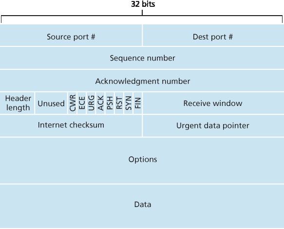
图3.29 TCP 报文段结构
作为教师,我们的经验是学生有时觉得包格式的讨论比较枯燥乏味。如果你喜欢乐高™,可以看看 [Pomeranz 2010] 中对 TCP 头部字段的趣味介绍。
Having taken a brief look at the TCP connection, let’s examine the TCP segment structure. The TCP segment consists of header fields and a data field. The data field contains a chunk of application data. As mentioned above, the MSS limits the maximum size of a segment’s data field. When TCP sends a large file, such as an image as part of a Web page, it typically breaks the file into chunks of size MSS (except for the last chunk, which will often be less than the MSS). Interactive applications, however, often transmit data chunks that are smaller than the MSS; for example, with remote login applications like Telnet, the data field in the TCP segment is often only one byte. Because the TCP header is typically 20 bytes (12 bytes more than the UDP header), segments sent by Telnet may be only 21 bytes in length.
Figure 3.29 shows the structure of the TCP segment. As with UDP, the header includes source and destination port numbers, which are used for multiplexing/demultiplexing data from/to upper-layer applications. Also, as with UDP, the header includes a checksum field. A TCP segment header also contains the following fields:
The 32-bit sequence number field and the 32-bit acknowledgment number field are used by the TCP sender and receiver in implementing a reliable data transfer service, as discussed below.
The 16-bit receive window field is used for flow control. We will see shortly that it is used to indicate the number of bytes that a receiver is willing to accept.
The 4-bit header length field specifies the length of the TCP header in 32-bit words. The TCP header can be of variable length due to the TCP options field. (Typically, the options field is empty, so that the length of the typical TCP header is 20 bytes.) - The optional and variable-length options field is used when a sender and receiver negotiate the
maximum segment size (MSS) or as a window scaling factor for use in high-speed networks. A time- stamping option is also defined. See RFC 854 and RFC 1323 for additional details. - The flag field contains 6 bits. The ACK bit is used to indicate that the value carried in the acknowledgment field is valid; that is, the segment contains an acknowledgment for a segment that has been successfully received. The RST, SYN, and FIN bits are used for connection setup and teardown, as we will discuss at the end of this section. The CWR and ECE bits are used in explicit congestion notification, as discussed in Section 3.7.2. Setting the PSH bit indicates that the receiver should pass the data to the upper layer immediately. Finally, the URG bit is used to indicate that there is data in this segment that the sending-side upper-layer entity has marked as “urgent.” The location of the last byte of this urgent data is indicated by the 16-bit urgent data pointer field. TCP must inform the receiving-side upper- layer entity when urgent data exists and pass it a pointer to the end of the urgent data. (In practice, the PSH, URG, and the urgent data pointer are not used. However, we mention these fields for completeness.)
Figure 3.29 TCP segment structure
Our experience as teachers is that our students sometimes find discussion of packet formats rather dry and perhaps a bit boring. For a fun and fanciful look at TCP header fields, particularly if you love Legos™ as we do, see [Pomeranz 2010].
序列号和确认号#
Sequence Numbers and Acknowledgment Numbers
TCP 报文段头中两个最重要的字段是序列号字段和确认号字段。这两个字段是 TCP 可靠数据传输服务的关键部分。但在讨论这些字段如何用于可靠传输之前,先解释 TCP 到底在这些字段中放了什么。
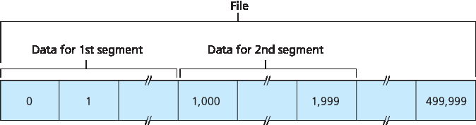
图3.30 将文件数据划分为 TCP 报文段
TCP 将数据视为无结构但有序的字节流。TCP 使用序列号反映了这一点,即序列号覆盖的是传输的字节流,而不是传输的报文段序列。因此, 一个报文段的序列号 是该报文段中第一个字节的字节流编号。举个例子,假设主机 A 上的一个进程想通过 TCP 连接向主机 B 上的一个进程发送数据流。主机 A 的 TCP 会隐式地为数据流中的每个字节编号。假设数据流是一个 50 万字节的文件,MSS 为 1000 字节,且数据流的第一个字节编号为 0。如 图3.30 所示,TCP 将数据流拆分为 500 个报文段。第一个报文段的序列号是 0,第二个为 1000,第三个为 2000,依此类推。每个序列号都被插入到相应 TCP 报文段头的序列号字段中。
现在来考虑确认号。这比序列号稍复杂。回想 TCP 是全双工的,因此主机 A 在向主机 B 发送数据的同时,可能也在从主机 B 接收数据(同一个 TCP 连接)。每个来自主机 B 的报文段都有其数据流(B 到 A)的序列号。主机 A 放入其发送报文段中的确认号是主机 A 期望从主机 B 接收的下一个字节的序列号。举几个例子帮助理解。假设主机 A 已接收了来自 B 的编号为 0 至 535 的所有字节,并且即将向 B 发送报文段。主机 A 正在等待序号为 536 及之后的字节,因此它在发给 B 的报文段的确认号字段中放 536。
再举一个例子,假设主机 A 收到了来自主机 B 的一个报文段,包含字节 0 至 535,另一个报文段包含字节 900 至 1000。由于某种原因,主机 A 尚未收到字节 536 至 899。在此例中,主机 A 仍在等待字节 536(及其后的字节)以重建 B 的数据流。因此,主机 A 发送给 B 的下一个报文段确认号仍为 536。由于 TCP 只确认字节流中第一个缺失字节之前的所有字节,TCP 被称为提供 累积确认。
这个例子也引出了一个重要但微妙的问题。主机 A 在收到包含字节 536 至 899 的第二个报文段之前,先收到了包含字节 900 至 1000 的第三个报文段。因此,第三个报文段是乱序到达的。问题是:主机在 TCP 连接中接收到乱序报文段时应如何处理?有趣的是,TCP RFC 并未对此做出规定,决定权留给实现 TCP 的程序员。基本上有两种选择:(1)接收方立即丢弃乱序报文段(这可以简化接收方设计),或(2)接收方保留乱序字节,等待缺失字节补齐。显然,后一种方法在网络带宽利用率上更高效,实际中也是采用此法。
在 图3.30 中,我们假设初始序列号为零。实际上,TCP 连接双方会随机选择初始序列号。这样做是为了尽量减少某个连接已终止但其报文段仍留在网络中时,这些旧报文段被误认为是同一对主机后续连接中的有效报文段(后续连接仍使用相同端口号)的可能性 [Sunshine 1978]。
Two of the most important fields in the TCP segment header are the sequence number field and the acknowledgment number field. These fields are a critical part of TCP’s reliable data transfer service. But before discussing how these fields are used to provide reliable data transfer, let us first explain what exactly TCP puts in these fields.
Figure 3.30 Dividing file data into TCP segments
TCP views data as an unstructured, but ordered, stream of bytes. TCP’s use of sequence numbers reflects this view in that sequence numbers are over the stream of transmitted bytes and not over the series of transmitted segments. The sequence number for a segment is therefore the byte-stream number of the first byte in the segment. Let’s look at an example. Suppose that a process in Host A wants to send a stream of data to a process in Host B over a TCP connection. The TCP in Host A will implicitly number each byte in the data stream. Suppose that the data stream consists of a file consisting of 500,000 bytes, that the MSS is 1,000 bytes, and that the first byte of the data stream is numbered 0. As shown in Figure 3.30, TCP constructs 500 segments out of the data stream. The first segment gets assigned sequence number 0, the second segment gets assigned sequence number 1,000, the third segment gets assigned sequence number 2,000, and so on. Each sequence number is inserted in the sequence number field in the header of the appropriate TCP segment.
Now let’s consider acknowledgment numbers. These are a little trickier than sequence numbers. Recall that TCP is full-duplex, so that Host A may be receiving data from Host B while it sends data to Host B (as part of the same TCP connection). Each of the segments that arrive from Host B has a sequence number for the data flowing from B to A. The acknowledgment number that Host A puts in its segment is the sequence number of the next byte Host A is expecting from Host B. It is good to look at a few examples to understand what is going on here. Suppose that Host A has received all bytes numbered 0 through 535 from B and suppose that it is about to send a segment to Host B. Host A is waiting for byte 536 and all the subsequent bytes in Host B’s data stream. So Host A puts 536 in the acknowledgment number field of the segment it sends to B.
As another example, suppose that Host A has received one segment from Host B containing bytes 0 through 535 and another segment containing bytes 900 through 1,000. For some reason Host A has not yet received bytes 536 through 899. In this example, Host A is still waiting for byte 536 (and beyond) in order to re-create B’s data stream. Thus, A’s next segment to B will contain 536 in the acknowledgment number field. Because TCP only acknowledges bytes up to the first missing byte in the stream, TCP is said to provide cumulative acknowledgments.
This last example also brings up an important but subtle issue. Host A received the third segment (bytes 900 through 1,000) before receiving the second segment (bytes 536 through 899). Thus, the third segment arrived out of order. The subtle issue is: What does a host do when it receives out-of-order segments in a TCP connection? Interestingly, the TCP RFCs do not impose any rules here and leave the decision up to the programmers implementing a TCP implementation. There are basically two choices: either (1) the receiver immediately discards out-of-order segments (which, as we discussed earlier, can simplify receiver design), or (2) the receiver keeps the out-of-order bytes and waits for the missing bytes to fill in the gaps. Clearly, the latter choice is more efficient in terms of network bandwidth, and is the approach taken in practice.
In Figure 3.30, we assumed that the initial sequence number was zero. In truth, both sides of a TCP connection randomly choose an initial sequence number. This is done to minimize the possibility that a segment that is still present in the network from an earlier, already-terminated connection between two hosts is mistaken for a valid segment in a later connection between these same two hosts (which also happen to be using the same port numbers as the old connection) [Sunshine 1978].
Telnet:序列号和确认号的案例研究#
Telnet: A Case Study for Sequence and Acknowledgment Numbers
Telnet 定义于 RFC 854,是一种流行的应用层协议,用于远程登录。它运行在 TCP 之上,设计用于任意一对主机之间。与 第2章 中讨论的大容量数据传输应用不同,Telnet 是交互式应用。这里讨论 Telnet 例子,是因为它很好地说明了 TCP 的序列号和确认号。需要注意的是,现在许多用户更倾向于使用 SSH 协议而非 Telnet,因为 Telnet 连接中发送的数据(包括密码!)未加密,使得 Telnet 容易受到窃听攻击(如 第8.7节 所述)。
假设主机 A 发起与主机 B 的 Telnet 会话。由于主机 A 发起会话,它被称为客户端,主机 B 被称为服务器端。用户在客户端每输入一个字符,该字符就会发送到远程主机;远程主机会返回该字符的副本,并显示在 Telnet 用户的屏幕上。该“回显”用于确保用户看到的字符已被远程站点接收并处理。这样,每个字符从用户敲击按键到显示在用户屏幕上,要经过网络两次。
现在假设用户输入了一个字母‘C’,然后去喝咖啡。我们来看看客户端和服务器之间传输的 TCP 报文段。如 图3.31 所示,假设客户端和服务器的起始序列号分别为 42 和 79。回想一下,报文段的序列号是数据字段中第一个字节的序列号。因此,客户端发送的第一个报文段序列号为 42;服务器发送的第一个报文段序列号为 79。确认号是主机期待接收的下一个字节的序列号。在 TCP 连接建立后但数据传送前,客户端期待字节 79,服务器期待字节 42。
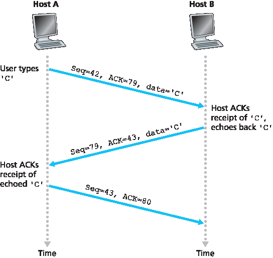
图3.31 简单 Telnet 应用中的 TCP 序列号和确认号
如 图3.31 所示,发送了三个报文段。第一个报文段由客户端发送到服务器,数据字段包含字母‘C’的 1 字节 ASCII 码。该报文段序列号字段为 42,正如前述。此外,因为客户端尚未收到来自服务器的数据,该报文段的确认号字段为 79。
第二个报文段由服务器发送到客户端,具有双重作用。首先,它确认服务器已收到的数据。通过在确认字段中放置 43,服务器告知客户端它已成功接收到字节 42 及之前的数据,并正在等待字节 43 及以后的数据。第二个作用是回显字母‘C’,因此该报文段的数据字段中含有‘C’的 ASCII 码。该报文段序列号为 79,这是服务器向客户端发送数据流的初始序列号,因为这是服务器发送的第一个数据字节。注意,客户端到服务器的数据确认是携带在服务器到客户端数据的报文段中的,这种确认称为 搭载确认。
第三个报文段由客户端发送到服务器,唯一目的是确认它已收到服务器的数据。(回想第二个报文段中含有服务器发送给客户端的‘C’字符数据。)该报文段数据字段为空(即确认没有与任何客户端到服务器数据搭载)。确认号字段为 80,因为客户端已收到序号最高为 79 的字节流,现在期待字节 80 及以后的数据。你可能会觉得奇怪,这个报文段虽然没有数据,却依然有序列号。但因为 TCP 必须包含序列号字段,所以该报文段需要有一个序列号。
Telnet, defined in RFC 854, is a popular application-layer protocol used for remote login. It runs over TCP and is designed to work between any pair of hosts. Unlike the bulk data transfer applications discussed in Chapter 2, Telnet is an interactive application. We discuss a Telnet example here, as it nicely illustrates TCP sequence and acknowledgment numbers. We note that many users now prefer to use the SSH protocol rather than Telnet, since data sent in a Telnet connection (including passwords!) are not encrypted, making Telnet vulnerable to eavesdropping attacks (as discussed in Section 8.7).
Suppose Host A initiates a Telnet session with Host B. Because Host A initiates the session, it is labeled the client, and Host B is labeled the server. Each character typed by the user (at the client) will be sent to the remote host; the remote host will send back a copy of each character, which will be displayed on the Telnet user’s screen. This “echo back” is used to ensure that characters seen by the Telnet user have already been received and processed at the remote site. Each character thus traverses the network twice between the time the user hits the key and the time the character is displayed on the user’s monitor.
Now suppose the user types a single letter, ‘C,’ and then grabs a coffee. Let’s examine the TCP segments that are sent between the client and server. As shown in Figure 3.31, we suppose the starting sequence numbers are 42 and 79 for the client and server, respectively. Recall that the sequence number of a segment is the sequence number of the first byte in the data field. Thus, the first segment sent from the client will have sequence number 42; the first segment sent from the server will have sequence number 79. Recall that the acknowledgment number is the sequence number of the next byte of data that the host is waiting for. After the TCP connection is established but before any data is sent, the client is waiting for byte 79 and the server is waiting for byte 42.
Figure 3.31 Sequence and acknowledgment numbers for a simple Telnet application over TCP
As shown in Figure 3.31, three segments are sent. The first segment is sent from the client to the server, containing the 1-byte ASCII representation of the letter ‘C’ in its data field. This first segment also has 42 in its sequence number field, as we just described. Also, because the client has not yet received any data from the server, this first segment will have 79 in its acknowledgment number field.
The second segment is sent from the server to the client. It serves a dual purpose. First it provides an acknowledgment of the data the server has received. By putting 43 in the acknowledgment field, the server is telling the client that it has successfully received everything up through byte 42 and is now waiting for bytes 43 onward. The second purpose of this segment is to echo back the letter ‘C.’ Thus, the second segment has the ASCII representation of ‘C’ in its data field. This second segment has the sequence number 79, the initial sequence number of the server-to-client data flow of this TCP connection, as this is the very first byte of data that the server is sending. Note that the acknowledgment for client-to-server data is carried in a segment carrying server-to-client data; this acknowledgment is said to be piggybacked on the server-to-client data segment.
The third segment is sent from the client to the server. Its sole purpose is to acknowledge the data it has received from the server. (Recall that the second segment contained data—the letter ‘C’—from the server to the client.) This segment has an empty data field (that is, the acknowledgment is not being piggybacked with any client-to-server data). The segment has 80 in the acknowledgment number field because the client has received the stream of bytes up through byte sequence number 79 and it is now waiting for bytes 80 onward. You might think it odd that this segment also has a sequence number since the segment contains no data. But because TCP has a sequence number field, the segment needs to have some sequence number.
3.5.3 往返时间估计与超时#
3.5.3 Round-Trip Time Estimation and Timeout
TCP,像我们在 第3.4节 中的 rdt 协议一样,使用超时/重传机制来恢复丢失的报文段。虽然这个机制在概念上很简单,但在实际协议如 TCP 中实现超时/重传机制时会出现许多细微问题。或许最明显的问题是超时间隔的长度。显然,超时应大于连接的往返时间(RTT),即从发送报文段到收到确认的时间。否则,会产生不必要的重传。但到底要多大呢?RTT 应该如何估计?是否应为每个未确认的报文段设置定时器?问题很多!本节讨论基于 [Jacobson 1988] 中的 TCP 研究和当前 IETF 关于 TCP 定时器管理的建议 [RFC 6298]。
TCP, like our rdt protocol in Section 3.4, uses a timeout/retransmit mechanism to recover from lost
segments. Although this is conceptually simple, many subtle issues arise when we implement a
timeout/retransmit mechanism in an actual protocol such as TCP. Perhaps the most obvious question is
the length of the timeout intervals. Clearly, the timeout should be larger than the connection’s round-trip
time (RTT), that is, the time from when a segment is sent until it is acknowledged. Otherwise,
unnecessary retransmissions would be sent. But how much larger? How should the RTT be estimated in
the first place? Should a timer be associated with each and every unacknowledged segment? So many
questions! Our discussion in this section is based on the TCP work in [Jacobson 1988] and the current
IETF recommendations for managing TCP timers [RFC 6298].
估计往返时间#
Estimating the Round-Trip Time
让我们从 TCP 定时器管理的研究开始,考虑 TCP 如何估计发送端和接收端之间的往返时间。实现方法如下。一个报文段的样本 RTT,记为 SampleRTT,是从该报文段被发送(即交给 IP)到收到该报文段确认的时间间隔。大多数 TCP 实现不会为每个传输的报文段测量 SampleRTT,而是在任何时刻只测量一个未确认报文段的 SampleRTT,因此大约每个 RTT 会获得一个新的 SampleRTT。此外,TCP 不会为重传的报文段计算 SampleRTT;只测量首次传输的报文段 [Karn 1987]。(本章末的习题会让你考虑原因。)
显然,由于路由器拥塞和终端系统负载变化, SampleRTT 会在报文段间波动。为估计典型的 RTT,自然需要对 SampleRTT 取某种平均。TCP 维护一个称为 EstimatedRTT 的平均值。当获得新的 SampleRTT 时,TCP 根据以下公式更新 EstimatedRTT:
EstimatedRTT=(1-α)⋅EstimatedRTT+α⋅SampleRTT
上式用编程语言形式表达—— EstimatedRTT 的新值是之前 EstimatedRTT 与新的 SampleRTT 的加权组合。推荐的 α 值为 α=0.125(即 1/8):rfc:6298,此时公式为:
EstimatedRTT=0.875⋅EstimatedRTT+0.125⋅SampleRTT
注意, EstimatedRTT 是 SampleRTT 的加权平均。正如本章末的习题所述,这种加权平均对最近样本赋予更大权重,反映最近样本更能体现当前网络拥塞状况。在统计学中,这种平均称为 指数加权移动平均(EWMA) 。其“指数”指的是随着更新进行,某个 SampleRTT 权重呈指数衰减。在习题中你将被要求推导 EstimatedRTT 中的指数项。
图 3.32 展示了来自 gaia.cs.umass.edu (马萨诸塞州阿默斯特)到 fantasia.eurecom.fr (法国南部)的一次 TCP 连接的 SampleRTT 和 α=1/8 时的 EstimatedRTT。显然, SampleRTT 的变化在 EstimatedRTT 计算中被平滑。
除了 RTT 的估计值,衡量 RTT 的变化度也很有价值。[RFC 6298] 定义了 RTT 变化, DevRTT,用于估计 SampleRTT 通常偏离 EstimatedRTT 的程度:
DevRTT=(1−β)⋅DevRTT+β⋅|SampleRTT−EstimatedRTT|
注意, DevRTT 是 SampleRTT 和 EstimatedRTT 差值的 EWMA。如果 SampleRTT 波动较小,则 DevRTT 也小;反之,波动大时 DevRTT 也大。推荐的 β 值为 0.25。
Let’s begin our study of TCP timer management by considering how TCP estimates the round-trip time
between sender and receiver. This is accomplished as follows. The sample RTT, denoted SampleRTT ,
for a segment is the amount of time between when the segment is sent (that is, passed to IP) and when
an acknowledgment for the segment is received. Instead of measuring a SampleRTT for every
transmitted segment, most TCP implementations take only one SampleRTT measurement at a time.
That is, at any point in time, the SampleRTT is being estimated for only one of the transmitted but
currently unacknowledged segments, leading to a new value of SampleRTT approximately once every
RTT. Also, TCP never computes a SampleRTT for a segment that has been retransmitted; it only
measures SampleRTT for segments that have been transmitted once [Karn 1987]. (A problem at the
end of the chapter asks you to consider why.)
Obviously, the SampleRTT values will fluctuate from segment to segment due to congestion in the
routers and to the varying load on the end systems. Because of this fluctuation, any given SampleRTT
value may be atypical. In order to estimate a typical RTT, it is therefore natural to take some sort of
average of the SampleRTT values. TCP maintains an average, called EstimatedRTT , of the
SampleRTT values. Upon obtaining a new SampleRTT , TCP updates EstimatedRTT according to
the following formula:
EstimatedRTT=(1−α)⋅EstimatedRTT+α⋅SampleRTT
The formula above is written in the form of a programming-language statement—the new value of EstimatedRTT is a weighted combination of the previous value of EstimatedRTT and the new value for SampleRTT. The recommended value of α is α = 0.125 (that is, 1/8) [RFC 6298], in which case the formula above becomes:
EstimatedRTT=0.875⋅EstimatedRTT+0.125⋅SampleRTT
Note that EstimatedRTT is a weighted average of the SampleRTT values. As discussed in a homework
problem at the end of this chapter, this weighted average puts more weight on recent samples than on
old samples. This is natural, as the more recent samples better reflect the current congestion in the
network. In statistics, such an average is called an exponential weighted moving average (EWMA).
The word “exponential” appears in EWMA because the weight of a given SampleRTT decays
exponentially fast as the updates proceed. In the homework problems you will be asked to derive the
exponential term in EstimatedRTT .
Figure 3.32 shows the SampleRTT values and EstimatedRTT for a value of α = 1/8 for a TCP
connection between gaia.cs.umass.edu (in Amherst, Massachusetts) to fantasia.eurecom.fr
(in the south of France). Clearly, the variations in the SampleRTT are smoothed out in the computation
of the EstimatedRTT .
In addition to having an estimate of the RTT, it is also valuable to have a measure of the variability of the
RTT. [RFC 6298] defines the RTT variation, DevRTT , as an estimate of how much SampleRTT
typically deviates from EstimatedRTT :
DevRTT=(1−β)⋅DevRTT+β⋅|SampleRTT−EstimatedRTT|
Note that DevRTT is an EWMA of the difference between SampleRTT and EstimatedRTT . If the
SampleRTT values have little fluctuation, then DevRTT will be small; on the other hand, if there is a lot
of fluctuation, DevRTT will be large. The recommended value of β is 0.25.
设置与管理重传超时间隔#
Setting and Managing the Retransmission Timeout Interval
给定 EstimatedRTT 和 DevRTT 的值,应为 TCP 的超时间隔使用什么值?显然,超时间隔应大于或等于 EstimatedRTT,否则会产生不必要的重传。但超时间隔不应远大于 EstimatedRTT;否则当报文段丢失时,TCP 不会迅速重传该报文段,导致数据传输延迟过大。因此,超时应设为 EstimatedRTT 加上一定的余量。当 SampleRTT 值波动大时,余量应较大;波动小时,余量应较小。因此 DevRTT 的值应在此起作用。所有这些考虑都被纳入 TCP 确定重传超时间隔的方法中:
TimeoutInterval=EstimatedRTT+4⋅DevRTT
实践中的原则
TCP 通过使用肯定确认和定时器来提供可靠的数据传输,方式与我们在 第3.4节 中研究的类似。TCP 确认已正确接收的数据,并在认为报文段或其对应确认丢失或损坏时重传这些报文段。某些版本的 TCP 还具有隐式 NAK 机制——通过 TCP 的快速重传机制,接收到针对某报文段的三个重复确认即作为对后续报文段的隐式 NAK,触发该报文段的重传而无需等待超时。TCP 使用序列号让接收方识别丢失或重复的报文段。正如我们的可靠数据传输协议 rdt3.0 中一样,TCP 本身无法确定报文段或其确认是否丢失、损坏或延迟过久。发送方对此的响应都是:重传该报文段。
TCP 还使用流水线技术,允许发送方同时有多个已发送但尚未确认的报文段存在。我们之前看到,当报文段大小与往返时延之比小的时候,流水线技术能显著提升会话吞吐量。发送方可以有多少个未确认的报文段,取决于 TCP 的流量控制和拥塞控制机制。TCP 流量控制将在本节末尾讨论;TCP 拥塞控制将在 第3.7节 讨论。目前,我们只需知道 TCP 发送方使用流水线技术。
推荐的初始 TimeoutInterval 值为 1 秒 [RFC 6298]。此外,当发生超时时, TimeoutInterval 值将加倍,以避免对即将被确认的后续报文段发生过早超时。但一旦收到报文段并更新了 EstimatedRTT, TimeoutInterval 将再次使用上述公式计算。
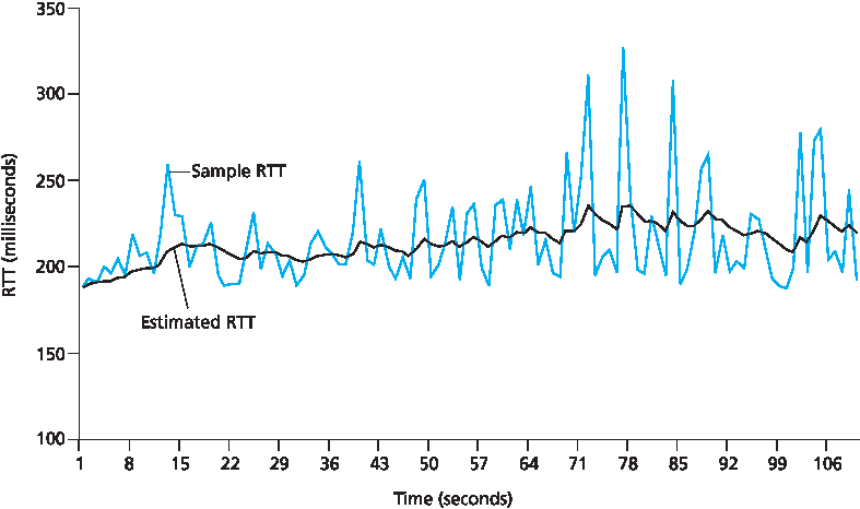
图 3.32 RTT 样本与 RTT 估计
Given values of EstimatedRTT and DevRTT , what value should be used for TCP’s timeout interval?
Clearly, the interval should be greater than or equal to EstimatedRTT , or unnecessary retransmissions would be sent. But the timeout interval should not be
too much larger than EstimatedRTT ; otherwise, when a segment is lost, TCP would not quickly
retransmit the segment, leading to large data transfer delays. It is therefore desirable to set the timeout
equal to the EstimatedRTT plus some margin. The margin should be large when there is a lot of
fluctuation in the SampleRTT values; it should be small when there is little fluctuation. The value of
DevRTT should thus come into play here. All of these considerations are taken into account in TCP’s
method for determining the retransmission timeout interval:
TimeoutInterval=EstimatedRTT+4⋅DevRTT
PRINCIPLES IN PRACTICE
TCP provides reliable data transfer by using positive acknowledgments and timers in much the same way that we studied in Section 3.4. TCP acknowledges data that has been received correctly, and it then retransmits segments when segments or their corresponding acknowledgments are thought to be lost or corrupted. Certain versions of TCP also have an implicit NAK mechanism—with TCP’s fast retransmit mechanism, the receipt of three duplicate ACKs for a given segment serves as an implicit NAK for the following segment, triggering retransmission of that segment before timeout. TCP uses sequences of numbers to allow the receiver to identify lost or duplicate segments. Just as in the case of our reliable data transfer protocol, rdt3.0 , TCP cannot itself tell for certain if a segment, or its ACK, is lost, corrupted, or overly delayed. At the sender, TCP’s response will be the same: retransmit the segment in question.
TCP also uses pipelining, allowing the sender to have multiple transmitted but yet-to-be- acknowledged segments outstanding at any given time. We saw earlier that pipelining can greatly improve a session’s throughput when the ratio of the segment size to round-trip delay is small. The specific number of outstanding, unacknowledged segments that a sender can have is determined by TCP’s flow-control and congestion-control mechanisms. TCP flow control is discussed at the end of this section; TCP congestion control is discussed in Section 3.7. For the time being, we must simply be aware that the TCP sender uses pipelining.
An initial TimeoutInterval value of 1 second is recommended [RFC 6298]. Also, when a timeout
occurs, the value of TimeoutInterval is doubled to avoid a premature timeout occurring for a
subsequent segment that will soon be acknowledged. However, as soon as a segment is received and
EstimatedRTT is updated, the TimeoutInterval is again computed using the formula above.
Figure 3.32 RTT samples and RTT estimates
3.5.4 可靠数据传输#
3.5.4 Reliable Data Transfer
回想一下,互联网的网络层服务(IP服务)是不可靠的。IP 不保证数据报的交付,不保证数据报的有序交付,也不保证数据报中数据的完整性。使用 IP 服务时,数据报可能会因路由器缓冲区溢出而无法到达目的地,数据报可能会乱序到达,且数据报中的比特可能被损坏(从0变为1,反之亦然)。由于传输层报文段是通过 IP 数据报在网络中传输的,传输层报文段同样可能遭受这些问题。
TCP 在 IP 不可靠的尽力而为服务之上创建了一个 可靠数据传输服务。TCP 的可靠数据传输服务确保一个进程从其 TCP 接收缓冲区读取的数据流是未损坏的、没有缺口的、无重复的且有序的;也就是说,字节流与连接另一端的系统所发送的字节流完全相同。TCP 如何提供可靠数据传输涉及许多我们在 第3.4节 学习的原理。
在我们之前关于可靠数据传输技术的发展中,概念上最容易假设为每个已发送但尚未确认的报文段关联一个单独的定时器。虽然理论上这样很好,但定时器管理可能带来相当大的开销。因此,推荐的 TCP 定时器管理程序 [RFC 6298] 只使用一个重传定时器,即使有多个已发送但尚未确认的报文段。本节描述的 TCP 协议遵循这一单定时器建议。
我们将分两步讨论 TCP 如何提供可靠数据传输。首先介绍一个仅使用超时重传丢失报文段的 TCP 发送方的高度简化描述;然后介绍一个更完整的描述,除了超时外还利用重复确认。在接下来的讨论中,假设数据仅单方向发送,从主机 A 到主机 B,且主机 A 发送一个大文件。
图3.33 展示了 TCP 发送方的高度简化描述。可以看到,TCP 发送方与数据传输和重传相关的三个主要事件为:来自上层应用的数据到达;定时器超时;确认(ACK)到达。第一个主要事件发生时,TCP 从应用层接收数据,将数据封装到报文段中,并将报文段传递给 IP。注意每个报文段都包含一个序列号,该序列号是报文段中第一个数据字节的字节流编号,如 第3.5.2节 所述。还要注意,如果定时器当前未为其他报文段运行,则当报文段传递给 IP 时 TCP 会启动定时器。(可将定时器视为与最早未确认报文段相关联。)该定时器的超时间隔为 TimeoutInterval,其由 EstimatedRTT 和 DevRTT 计算得出,详见 第3.5.3节。
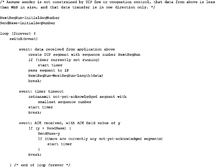
图 3.33 简化的 TCP 发送方
第二个主要事件是超时。TCP 对超时事件的响应是重传导致超时的报文段,然后重新启动定时器。
第三个必须处理的主要事件是来自接收方的确认报文段(ACK)(更具体地说,是包含有效 ACK 字段值的报文段)到达。该事件发生时,TCP 将确认值 y 与其变量 SendBase 进行比较。TCP 状态变量 SendBase 是最早未确认字节的序列号。(因此 SendBase-1 是接收方已正确且按序接收的最后一个字节的序列号。)如前所述,TCP 使用累积确认,因此 y 确认接收到字节号小于 y 的所有字节。如果 y > SendBase,则该确认确认了一个或多个之前未确认的报文段。因此发送方更新其 SendBase 变量;如果当前还有未确认报文段,则重新启动定时器。
Recall that the Internet’s network-layer service (IP service) is unreliable. IP does not guarantee datagram delivery, does not guarantee in-order delivery of datagrams, and does not guarantee the integrity of the data in the datagrams. With IP service, datagrams can overflow router buffers and never reach their destination, datagrams can arrive out of order, and bits in the datagram can get corrupted (flipped from 0 to 1 and vice versa). Because transport-layer segments are carried across the network by IP datagrams, transport-layer segments can suffer from these problems as well.
TCP creates a reliable data transfer service on top of IP’s unreliable best-effort service. TCP’s reliable data transfer service ensures that the data stream that a process reads out of its TCP receive buffer is uncorrupted, without gaps, without duplication, and in sequence; that is, the byte stream is exactly the same byte stream that was sent by the end system on the other side of the connection. How TCP provides a reliable data transfer involves many of the principles that we studied in Section 3.4.
In our earlier development of reliable data transfer techniques, it was conceptually easiest to assumethat an individual timer is associated with each transmitted but not yet acknowledged segment. While this is great in theory, timer management can require considerable overhead. Thus, the recommended TCP timer management procedures [RFC 6298] use only a single retransmission timer, even if there are multiple transmitted but not yet acknowledged segments. The TCP protocol described in this section follows this single-timer recommendation.
We will discuss how TCP provides reliable data transfer in two incremental steps. We first present a highly simplified description of a TCP sender that uses only timeouts to recover from lost segments; we then present a more complete description that uses duplicate acknowledgments in addition to timeouts. In the ensuing discussion, we suppose that data is being sent in only one direction, from Host A to Host B, and that Host A is sending a large file.
Figure 3.33 presents a highly simplified description of a TCP sender. We see that there are three major
events related to data transmission and retransmission in the TCP sender: data received from
application above; timer timeout; and ACK receipt. Upon the occurrence of the first major event, TCP receives data from the application,
encapsulates the data in a segment, and passes the segment to IP. Note that each segment includes a
sequence number that is the byte-stream number of the first data byte in the segment, as described in
Section 3.5.2. Also note that if the timer is already not running for some other segment, TCP starts the
timer when the segment is passed to IP. (It is helpful to think of the timer as being associated with the
oldest unacknowledged segment.) The expiration interval for this timer is the TimeoutInterval ,
which is calculated from EstimatedRTT and DevRTT , as described in Section 3.5.3.
Figure 3.33 Simplified TCP sender
The second major event is the timeout. TCP responds to the timeout event by retransmitting the segment that caused the timeout. TCP then restarts the timer.
The third major event that must be handled by the TCP sender is the arrival of an acknowledgment
segment (ACK) from the receiver (more specifically, a segment containing a valid ACK field value). On
the occurrence of this event, TCP compares the ACK value y with its variable SendBase . The TCP
state variable SendBase is the sequence number of the oldest unacknowledged byte. (Thus
SendBase-1 is the sequence number of the last byte that is known to have been received correctly
and in order at the receiver.) As indicated earlier, TCP uses cumulative acknowledgments, so that y
acknowledges the receipt of all bytes before byte number y . If y > SendBase , then the ACK is
acknowledging one or more previously unacknowledged segments. Thus the sender updates its
SendBase variable; it also restarts the timer if there currently are any not-yet-acknowledged segments.
几个有趣的场景#
A Few Interesting Scenarios
我们刚才描述了 TCP 提供可靠数据传输的高度简化版本。但即便是这个简化版本也有很多细节。为了更好地理解该协议的工作机制,下面通过几个简单的场景演示。图3.34 描绘了第一个场景,其中主机 A 向主机 B 发送一个报文段。假设该报文段序列号为 92,包含 8 字节数据。发送后,主机 A 等待来自主机 B 序列号为 100 的确认。虽然主机 B 收到了主机 A 的报文段,但主机 B 发送给主机 A 的确认报文丢失了。在这种情况下,会发生超时事件,主机 A 重传该报文段。当然,主机 B 收到重传时,根据序列号判断报文段中包含的数据已经收到,因此会丢弃该重传报文段中的字节。
在第二个场景中,见 图3.35,主机 A 连续发送两个报文段。第一个报文段序列号为 92,包含 8 字节数据;第二个报文段序列号为 100,包含 20 字节数据。假设两个报文段均完整到达主机 B,主机 B 为每个报文段发送两个独立的确认。第一个确认的确认号为 100,第二个为 120。假设两个确认均未在超时前到达主机 A。当超时事件发生时,主机 A 重新发送序列号为 92 的第一个报文段,并重新启动定时器。只要第二个报文段的确认在新的超时前到达,则第二个报文段不会被重传。
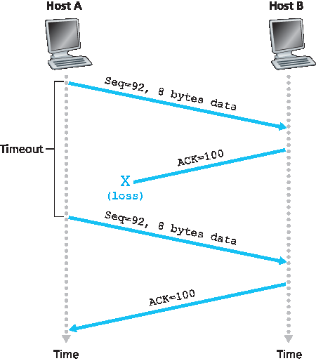
图 3.34 由于确认丢失导致的重传
第三个也是最后一个场景,假设主机 A 发送了两个报文段,情况与第二个例子完全相同。第一个报文段的确认在网络中丢失,但在超时事件发生前,主机 A 收到了确认号为 120 的确认。因此主机 A 知道主机 B 已接收到字节号直到 119 的所有数据,因此主机 A 不会重传这两个报文段。此场景见 图3.36。
We have just described a highly simplified version of how TCP provides reliable data transfer. But even this highly simplified version has many subtleties. To get a good feeling for how this protocol works, let’s now walk through a few simple scenarios. Figure 3.34 depicts the first scenario, in which Host A sends one segment to Host B. Suppose that this segment has sequence number 92 and contains 8 bytes of data. After sending this segment, Host A waits for a segment from B with acknowledgment number 100. Although the segment from A is received at B, the acknowledgment from B to A gets lost. In this case, the timeout event occurs, and Host A retransmits the same segment. Of course, when Host B receives the retransmission, it observes from the sequence number that the segment contains data that has already been received. Thus, TCP in Host B will discard the bytes in the retransmitted segment.
In a second scenario, shown in Figure 3.35, Host A sends two segments back to back. The first segment has sequence number 92 and 8 bytes of data, and the second segment has sequence number 100 and 20 bytes of data. Suppose that both segments arrive intact at B, and B sends two separate acknowledgments for each of these segments. The first of these acknowledgments has acknowledgment number 100; the second has acknowledgment number 120. Suppose now that neither of the acknowledgments arrives at Host A before the timeout. When the timeout event occurs, Host A resends the first segment with sequence number 92 and restarts the timer. As long as the ACK for the second segment arrives before the new timeout, the second segment will not be retransmitted.
Figure 3.34 Retransmission due to a lost acknowledgment
In a third and final scenario, suppose Host A sends the two segments, exactly as in the second example. The acknowledgment of the first segment is lost in the network, but just before the timeout event, Host A receives an acknowledgment with acknowledgment number 120. Host A therefore knows that Host B has received everything up through byte 119; so Host A does not resend either of the two segments. This scenario is illustrated in Figure 3.36.
超时间隔加倍#
Doubling the Timeout Interval
接下来讨论大多数 TCP 实现采用的一些修改。第一个修改涉及定时器超时后的超时间隔长度。此修改中,每当超时事件发生,TCP 会重传序列号最小的尚未确认报文段,如上所述。但每次重传后,TCP 将下一次超时间隔设置为上一次的两倍,而非从最新的 EstimatedRTT 和 DevRTT 计算得出(如 第3.5.3节 描述)。例如,假设最早未确认报文段关联的 TimeoutInterval 在定时器首次超时时为 0.75 秒,TCP 会重传该报文段,并将新的超时设置为 1.5 秒。如果 1.5 秒后定时器再次超时,TCP 再次重传该报文段,将超时设置为 3.0 秒。如此,每次重传后超时间隔呈指数增长。然而,每当定时器因其他两个事件启动(即应用层数据到达或确认到达)时, TimeoutInterval 会根据最新的 EstimatedRTT 和 DevRTT 重新计算。
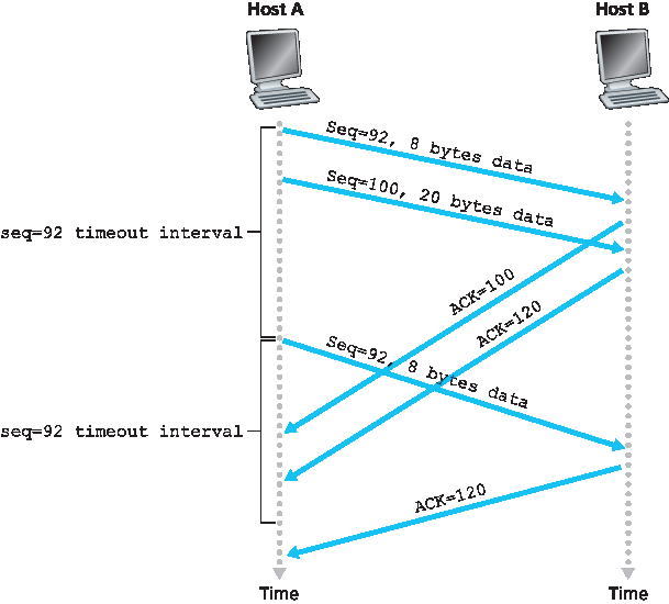
图 3.35 序列号 100 的报文段未被重传
该修改提供了一种有限形式的拥塞控制。(更全面的 TCP 拥塞控制将在 第3.7节 学习。)定时器超时很可能是由网络拥塞引起的,也就是说,在源与目的地之间路径上的一个或多个路由器队列中,过多的数据包到达导致数据包被丢弃和/或排队延迟过长。在拥塞时期,如果源端持续不断地重传数据包,拥塞可能会加剧。相反,TCP 会表现得更“礼貌”,每个发送方会在越来越长的时间间隔后重传。我们将在 第6章 学习以太网的 CSMA/CD 时看到类似的思路。
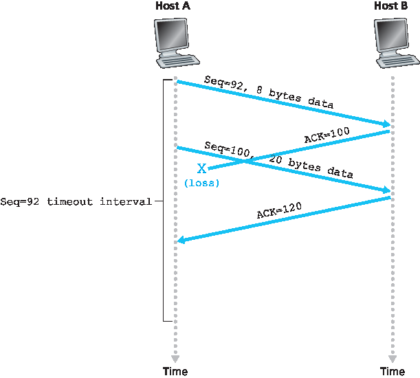
图 3.36 累积确认避免了第一个报文段的重传
We now discuss a few modifications that most TCP implementations employ. The first concerns the
length of the timeout interval after a timer expiration. In this modification, whenever the timeout event
occurs, TCP retransmits the not-yet-acknowledged segment with the smallest sequence number, as
described above. But each time TCP retransmits, it sets the next timeout interval to twice the previous
value, rather than deriving it from the last EstimatedRTT and DevRTT (as described in Section 3.5.3). For
example, suppose TimeoutInterval associated with the oldest not yet acknowledged segment is
.75 sec when the timer first expires. TCP will then retransmit this segment and set the new expiration
time to 1.5 sec. If the timer expires again 1.5 sec later, TCP will again retransmit this segment, now
setting the expiration time to 3.0 sec. Thus the intervals grow exponentially after each retransmission.
However, whenever the timer is started after either of the two other events (that is, data received from
application above, and ACK received), the TimeoutInterval is derived from the most recent values
of EstimatedRTT and DevRTT .
Figure 3.35 Segment 100 not retransmitted
This modification provides a limited form of congestion control. (More comprehensive forms of TCP congestion control will be studied in Section 3.7.) The timer expiration is most likely caused by congestion in the network, that is, too many packets arriving at one (or more) router queues in the path between the source and destination, causing packets to be dropped and/or long queuing delays. In times of congestion, if the sources continue to retransmit packets persistently, the congestion may get worse. Instead, TCP acts more politely, with each sender retransmitting after longer and longer intervals. We will see that a similar idea is used by Ethernet when we study CSMA/CD in Chapter 6.
Figure 3.36 A cumulative acknowledgment avoids retransmission of the first segment
快速重传#
Fast Retransmit
超时触发的重传存在的问题之一是超时时间可能相对较长。当报文段丢失时,这个较长的超时时间迫使发送方延迟重传丢失的数据包,从而增加端到端的延迟。幸运的是,发送方通常可以通过注意所谓的 重复确认(duplicate ACK) 在超时事件发生之前很早就检测到数据包丢失。重复确认是对发送方已经收到早先确认的报文段再次确认的 ACK。
要理解发送方对重复确认的响应,必须先了解接收方为什么会发送重复确认。表3.2 总结了 TCP 接收方的 ACK 生成策略 [RFC 5681]。当 TCP 接收方收到一个序列号大于下一个预期的按序序列号的报文段时,它检测到数据流中的一个缺口——即丢失的报文段。这个缺口可能是网络中报文段丢失或重排序的结果。由于 TCP 不使用负确认,接收方无法向发送方发送显式的负确认。相反,它只是对已按序接收到的最后一个字节再次确认(即生成重复确认)。 (注意 表3.2 允许接收方不丢弃乱序报文段的情况。)
表 3.2 TCP ACK 生成建议 [RFC 5681]
事件 |
TCP 接收方动作 |
|---|---|
到达带有预期序列号的按序报文段。此前所有数据已被确认。 |
延迟确认。等待最多 500 毫秒以接收下一个按序报文段。如果在此期间未收到,发送 ACK。 |
到达带有预期序列号的按序报文段。另有一个按序报文段等待确认。 |
立即发送一个累计确认,确认两个按序报文段。 |
到达带有高于预期序列号的乱序报文段。检测到缺口。 |
立即发送重复确认,指示下一个期望字节的序列号(即缺口的低端)。 |
到达部分或完全填补接收数据缺口的报文段。 |
立即发送 ACK,前提是该报文段从缺口低端开始。 |
由于发送方常常连续发送大量报文段,如果其中一个报文段丢失,极可能产生许多连续的重复确认。如果 TCP 发送方收到针对同一数据的三个重复确认,则认为紧跟被三次确认的报文段之后的报文段已丢失。(作业中会探讨为什么发送方等待三个重复确认而非单个重复确认。)当收到三个重复确认时,TCP 发送方执行 快速重传 [RFC 5681],在该报文段的定时器超时之前重传丢失的报文段。如 图3.37 所示,第二个报文段丢失,随后在定时器超时前被重传。对于带有快速重传的 TCP,以下代码片段替代了 图3.33 中的 ACK 收到事件:
event: 收到 ACK,ACK 字段值为 y

if (y > SendBase) {

    SendBase=y

    if (当前有未确认的报文段)
        启动定时器

    else {  /* 针对已确认报文段的重复 ACK */

        递增针对 y 收到的重复 ACK 数量

        if (针对 y 收到的重复 ACK 数量 == 3)

            /* TCP 快速重传 */
            重发序列号为 y 的报文段
    }
    break;
}
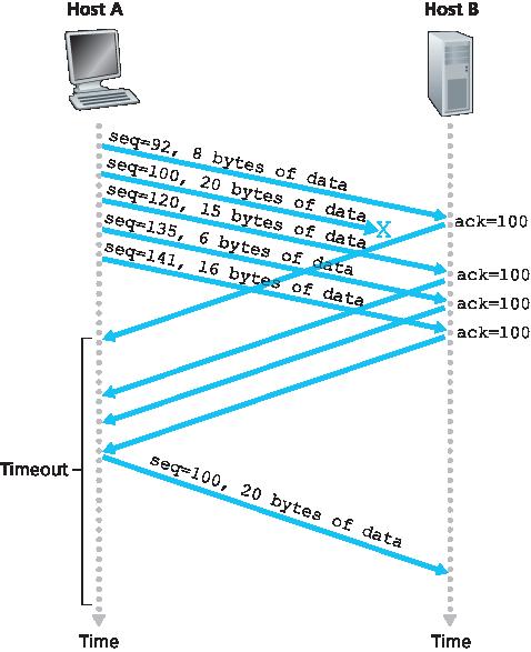
图 3.37 快速重传:在报文段定时器超时前重传丢失的报文段
我们之前提到,实际协议(如 TCP)中实现超时/重传机制时会出现许多细微问题。上述过程是在 TCP 定时器 20 多年经验基础上演化而成的,足以说明情况的复杂性!
One of the problems with timeout-triggered retransmissions is that the timeout period can be relatively long. When a segment is lost, this long timeout period forces the sender to delay resending the lost packet, thereby increasing the end-to-end delay. Fortunately, the sender can often detect packet loss well before the timeout event occurs by noting so-called duplicate ACKs. A duplicate ACK is an ACK that reacknowledges a segment for which the sender has already received an earlier acknowledgment. To understand the sender’s response to a duplicate ACK, we must look at why the receiver sends a duplicate ACK in the first place. Table 3.2 summarizes the TCP receiver’s ACK generation policy [RFC 5681]. When a TCP receiver receives a segment with a sequence number that is larger than the next, expected, in-order sequence number, it detects a gap in the data stream—that is, a missing segment. This gap could be the result of lost or reordered segments within the network. Since TCP does not use negative acknowledgments, the receiver cannot send an explicit negative acknowledgment back to the sender. Instead, it simply reacknowledges (that is, generates a duplicate ACK for) the last in-order byte of data it has received. (Note that Table 3.2 allows for the case that the receiver does not discard out-of-order segments.)
Table 3.2 TCP ACK Generation Recommendation [RFC 5681]
Because a sender often sends a large number of segments back to back, if one segment is lost, there will likely be many back-to-back duplicate ACKs. If the TCP sender receives three duplicate ACKs for the same data, it takes this as an indication that the segment following the segment that has been ACKed three times has been lost. (In the homework problems, we consider the question of why the sender waits for three duplicate ACKs, rather than just a single duplicate ACK.) In the case that three duplicate ACKs are received, the TCP sender performs a fast retransmit [RFC 5681], retransmitting the missing segment before that segment’s timer expires. This is shown in Figure 3.37, where the second segment is lost, then retransmitted before its timer expires. For TCP with fast retransmit, the following code snippet replaces the ACK received event in Figure 3.33:
event: ACK received, with ACK field value of y

if (y > SendBase) {

   SendBase=y

   if (there are currently any not yet
               acknowledged segments)
         start timer

   else {  /* a duplicate ACK for already ACKed segment */

         increment number of duplicate ACKs received for y

         if (number of duplicate ACKS received for y==3)

            /* TCP fast retransmit */
            resend segment with sequence number y
   }
   break;
}
Figure 3.37 Fast retransmit: retransmitting the missing segment before the segment’s timer expires
We noted earlier that many subtle issues arise when a timeout/retransmit mechanism is implemented in an actual protocol such as TCP. The procedures above, which have evolved as a result of more than 20 years of experience with TCP timers, should convince you that this is indeed the case!
回退 N 还是选择重传?#
Go-Back-N or Selective Repeat?
让我们以以下问题结束对 TCP 错误恢复机制的研究:TCP 是回退 N(GBN)协议还是选择重传(SR)协议?回想 TCP 确认是累计确认,且接收方不会单独确认按序之外但已正确接收的报文段。因此,如 图3.33)所示,TCP 发送方只需维护已发送但未确认的最小序列号( SendBase )和下一个要发送的字节序列号( NextSeqNum )。从这个意义上看,TCP 很像一个 GBN 协议。但 TCP 与 GBN 之间存在显著差异。许多 TCP 实现会缓存正确接收的乱序报文段 [Stevens 1994]。再考虑发送方连续发送序列号为 1、2、…、N 的报文段,且所有报文段都按序无误地到达接收方。假设序号为 n < N 的报文段的确认丢失,但其余 N-1 个确认均在超时前到达发送方。在这种情况下,GBN 会重传报文段 n 及其后所有报文段 n+1、n+2、…、N。而 TCP 最多只重传一个报文段,即报文段 n。更进一步,如果报文段 n+1 的确认在报文段 n 的超时前到达,TCP 甚至不会重传报文段 n。
TCP 的一个建议修改——所谓的 选择性确认(Selective Acknowledgment, SACK) [RFC 2018] 允许 TCP 接收方选择性确认乱序报文段,而不仅仅是累计确认最后一个正确接收的按序报文段。当结合选择性重传——跳过已经被选择性确认的报文段重传时,TCP 非常像我们通用的 SR 协议。因此,TCP 的错误恢复机制可能最好归类为 GBN 和 SR 协议的混合体。
Let us close our study of TCP’s error-recovery mechanism by considering the following question: Is TCP
a GBN or an SR protocol? Recall that TCP acknowledgments are cumulative and correctly received but
out-of-order segments are not individually ACKed by the receiver. Consequently, as shown in Figure 3.33 (see also Figure 3.19), the TCP sender need only maintain the smallest sequence number of a
transmitted but unacknowledged byte ( SendBase ) and the sequence number of the next byte to be
sent ( NextSeqNum ). In this sense, TCP looks a lot like a GBN-style protocol. But there are some
striking differences between TCP and Go-Back-N. Many TCP implementations will buffer correctly
received but out-of-order segments [Stevens 1994]. Consider also what happens when the sender
sends a sequence of segments 1, 2, …, N, and all of the segments arrive in order without error at the
receiver. Further suppose that the acknowledgment for packet n<N gets lost, but the remaining N−1
acknowledgments arrive at the sender before their respective timeouts. In this example, GBN would
retransmit not only packet n, but also all of the subsequent packets n+1,n+2,…,N. TCP, on the other
hand, would retransmit at most one segment, namely, segment n. Moreover, TCP would not even
retransmit segment n if the acknowledgment for segment n+1 arrived before the timeout for segment n.
A proposed modification to TCP, the so-called selective acknowledgment [RFC 2018], allows a TCP receiver to acknowledge out-of-order segments selectively rather than just cumulatively acknowledging the last correctly received, in-order segment. When combined with selective retransmission—skipping the retransmission of segments that have already been selectively acknowledged by the receiver—TCP looks a lot like our generic SR protocol. Thus, TCP’s error-recovery mechanism is probably best categorized as a hybrid of GBN and SR protocols.
3.5.5 流量控制#
3.5.5 Flow Control
回想一下,TCP 连接两端的主机都会为该连接预留一个接收缓冲区。当 TCP 连接接收到正确且按序的字节时,它将数据放入接收缓冲区。相关的应用进程会从该缓冲区读取数据,但不一定是在数据到达的瞬间。实际上,接收应用可能正在忙于其他任务,甚至直到数据到达很久之后才尝试读取数据。如果应用读取数据相对较慢,发送方很容易因发送过快而导致连接的接收缓冲区溢出。
TCP 为其应用程序提供了 流量控制服务,以消除发送方溢出接收方缓冲区的可能性。因此,流量控制是一种速率匹配服务——匹配发送方的发送速率与接收应用的读取速率。如前所述,TCP 发送方还可能因 IP 网络内的拥塞而被限制;这种发送方控制称为 拥塞控制,我们将在 第3.6节 和 第3.7节 中详细探讨。尽管流量控制和拥塞控制的动作类似(对发送方限速),但显然它们的原因截然不同。不幸的是,许多作者将这两个术语混用,精明的读者应予以区分。现在我们讨论 TCP 如何提供流量控制服务。为了看清全貌,我们在本节中假设 TCP 实现中接收方会丢弃乱序报文段。
TCP 通过让发送方维护一个变量,称为 接收窗口 来实现流量控制。非正式地说,接收窗口用于向发送方传达接收方缓冲区中有多少空闲空间。由于 TCP 是全双工的,连接双方的发送方各自维护不同的接收窗口。让我们以文件传输为背景来研究接收窗口。假设主机 A 通过 TCP 连接向主机 B 发送大文件。主机 B 为该连接分配一个接收缓冲区,记其大小为 RcvBuffer。主机 B 中的应用进程会不时从缓冲区读取数据。定义以下变量:
LastByteRead:主机 B 的应用进程从缓冲区读取的数据流中最后一个字节的编号
LastByteRcvd:数据流中已从网络到达并放入主机 B 接收缓冲区的最后一个字节编号
由于 TCP 不允许溢出分配的缓冲区,必须满足
LastByteRcvd - LastByteRead ≤ RcvBuffer
接收窗口,记为 rwnd,设置为缓冲区剩余空间大小:
rwnd = RcvBuffer - [LastByteRcvd - LastByteRead]
由于剩余空间随时间变化, rwnd 是动态的。变量 rwnd 如 图3.38 所示。
连接如何使用变量 rwnd 提供流量控制服务?主机 B 告诉主机 A 其连接缓冲区的剩余空间大小,方法是将当前的 rwnd 值放入发送给 A 的每个报文段的接收窗口字段。起初,主机 B 设置 rwnd = RcvBuffer。注意,为实现此功能,主机 B 必须跟踪若干连接特定变量。
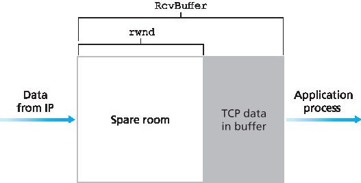
图 3.38 接收窗口(rwnd)和接收缓冲区(RcvBuffer)
主机 A 则跟踪两个变量, LastByteSent 和 LastByteAcked,含义显而易见。注意,这两个变量的差值 LastByteSent - LastByteAcked 表示 A 发送出去但尚未被确认的数据量。通过保持未确认数据量小于 rwnd,主机 A 确保不会溢出主机 B 的接收缓冲区。因此,主机 A 始终保证
LastByteSent - LastByteAcked ≤ rwnd
此方案存在一个小技术问题。假设主机 B 的接收缓冲区满了,因此 rwnd = 0。主机 B 将 rwnd = 0 通告给主机 A 后,且 B 没有数据要发送给 A。接下来会发生什么?由于 B 的应用进程开始清空缓冲区,但 TCP 仅在有数据或需要发送确认时才向主机 A 发送报文段,因此 TCP 不会发送携带新 rwnd 值的新报文段。结果,主机 A 不会被通知主机 B 缓冲区有空间腾出,主机 A 阻塞,无法继续发送数据!为解决此问题,TCP 规范要求当 B 的接收窗口为零时,主机 A 继续发送携带一个数据字节的报文段。这些报文段会被接收方确认,缓冲区开始清空后,确认中将包含非零的 rwnd 值。
本书在线站点 http://www.awl.com/kurose-ross 提供了一个交互式 Java 小程序,用以演示 TCP 接收窗口的工作原理。
描述完 TCP 的流量控制服务后,这里简要提及 UDP 不提供流量控制,因此接收方可能因缓冲区溢出而丢弃报文段。例如,考虑从主机 A 的进程向主机 B 的进程发送一系列 UDP 报文段。典型 UDP 实现中,UDP 会将报文段追加到有限大小的缓冲区中,该缓冲区位于对应套接字“之前”(即进程的入口)。进程每次从缓冲区读取一个完整的报文段。如果进程未能足够快地从缓冲区读取数据,缓冲区将溢出,导致报文段丢失。
Recall that the hosts on each side of a TCP connection set aside a receive buffer for the connection. When the TCP connection receives bytes that are correct and in sequence, it places the data in the receive buffer. The associated application process will read data from this buffer, but not necessarily at the instant the data arrives. Indeed, the receiving application may be busy with some other task and may not even attempt to read the data until long after it has arrived. If the application is relatively slow at reading the data, the sender can very easily overflow the connection’s receive buffer by sending too much data too quickly.
TCP provides a flow-control service to its applications to eliminate the possibility of the sender overflowing the receiver’s buffer. Flow control is thus a speed-matching service—matching the rate at which the sender is sending against the rate at which the receiving application is reading. As noted earlier, a TCP sender can also be throttled due to congestion within the IP network; this form of sender control is referred to as congestion control, a topic we will explore in detail in Sections 3.6 and 3.7. Even though the actions taken by flow and congestion control are similar (the throttling of the sender), they are obviously taken for very different reasons. Unfortunately, many authors use the terms interchangeably, and the savvy reader would be wise to distinguish between them. Let’s now discuss how TCP provides its flow-control service. In order to see the forest for the trees, we suppose throughout this section that the TCP implementation is such that the TCP receiver discards out-of-order segments.
TCP provides flow control by having the sender maintain a variable called the receive window. Informally, the receive window is used to give the sender an idea of how much free buffer space is available at the receiver. Because TCP is full-duplex, the sender at each side of the connection maintains a distinct receive window. Let’s investigate the receive window in the context of a file transfer. Suppose that Host A is sending a large file to Host B over a TCP connection. Host B allocates a receive buffer to this connection; denote its size by RcvBuffer. From time to time, the application process in Host B reads from the buffer. Define the following variables:
LastByteRead: the number of the last byte in the data stream read from the buffer by the application process in B
LastByteRcvd: the number of the last byte in the data stream that has arrived from the network and has been placed in the receive buffer at B
Because TCP is not permitted to overflow the allocated buffer, we must have
LastByteRcvd-LastByteRead≤RcvBuffer
The receive window, denoted rwnd is set to the amount of spare room in the buffer:
rwnd=RcvBuffer−[LastByteRcvd−LastByteRead]
Because the spare room changes with time, rwnd is dynamic. The variable rwnd is illustrated in Figure 3.38.
How does the connection use the variable rwnd to provide the flow-control service? Host B tells Host A how much spare room it has in the connection buffer by placing its current value of rwnd in the receive window field of every segment it sends to A. Initially, Host B sets rwnd = RcvBuffer. Note that to pull this off, Host B must keep track of several connection-specific variables.
Figure 3.38 The receive window (rwnd) and the receive buffer (RcvBuffer)
Host A in turn keeps track of two variables, LastByteSent and LastByteAcked, which have obvious meanings. Note that the difference between these two variables, LastByteSent – LastByteAcked, is the amount of unacknowledged data that A has sent into the connection. By keeping the amount of unacknowledged data less than the value of rwnd, Host A is assured that it is not overflowing the receive buffer at Host B. Thus, Host A makes sure throughout the connection’s life that
LastByteSent−LastByteAcked≤rwnd
There is one minor technical problem with this scheme. To see this, suppose Host B’s receive buffer
becomes full so that rwnd = 0. After advertising rwnd = 0 to Host A, also suppose that B has nothing to send to A. Now consider what happens. As the application process at B empties the buffer, TCP does not send new segments with new rwnd values to Host A; indeed, TCP sends a segment to Host A only if it has data to send or if it has an acknowledgment to send. Therefore, Host A is never informed that some space has opened up in Host B’s receive buffer—Host A is blocked and can transmit no more data! To solve this problem, the TCP specification requires Host A to continue to send segments with one data byte when B’s receive window is zero. These segments will be acknowledged by the receiver. Eventually the buffer will begin to empty and the acknowledgments will contain a nonzero rwnd value.
The online site at http://www.awl.com/kurose-ross for this book provides an interactive Java applet that illustrates the operation of the TCP receive window.
Having described TCP’s flow-control service, we briefly mention here that UDP does not provide flow control and consequently, segments may be lost at the receiver due to buffer overflow. For example, consider sending a series of UDP segments from a process on Host A to a process on Host B. For a typical UDP implementation, UDP will append the segments in a finite-sized buffer that “precedes” the corresponding socket (that is, the door to the process). The process reads one entire segment at a time from the buffer. If the process does not read the segments fast enough from the buffer, the buffer will overflow and segments will get dropped.
3.5.6 TCP 连接管理#
3.5.6 TCP Connection Management
本小节我们将仔细看看 TCP 连接是如何建立和拆除的。虽然这个话题看起来可能不算特别吸引人,但它很重要,因为 TCP 连接的建立会显著增加感知延迟(例如,在浏览网页时)。此外,许多最常见的网络攻击——包括极其流行的 SYN 洪泛攻击——都利用了 TCP 连接管理中的漏洞。我们先看看 TCP 连接是如何建立的。假设运行在一台主机上的进程(客户端)想要与另一台主机上的进程(服务器)建立连接。客户端应用进程首先通知客户端 TCP 它想要建立与服务器进程的连接。客户端的 TCP 然后按以下方式与服务器端的 TCP 建立连接:
步骤1。客户端 TCP 首先向服务器 TCP 发送一个特殊的 TCP 报文段。该特殊报文段不包含应用层数据。但报文段头部的一个标志位(见 图3.29),SYN 位,被置为1。因此,这个特殊报文段称为 SYN 报文段。此外,客户端随机选择一个初始序列号(
client_isn),并将该数值放入初始 TCP SYN 报文段的序列号字段。该报文段被封装在 IP 数据报中发送给服务器。关于如何正确随机选择client_isn以避免某些安全攻击的问题已有大量研究 [CERT 2001–09]。步骤2。一旦包含 TCP SYN 报文段的 IP 数据报到达服务器主机(假设确实到达!),服务器从数据报中提取 TCP SYN 报文段,分配连接所需的 TCP 缓冲区和变量,并向客户端 TCP 发送一个连接许可报文段。(我们将在 第8章 看到,在完成三次握手第三步之前分配这些缓冲区和变量使得 TCP 易受一种称为 SYN 洪泛的拒绝服务攻击影响。)这个连接许可报文段同样不包含应用层数据,但在报文段头部有三条重要信息。首先,SYN 位被置为1。其次,TCP 报文段头部的确认字段被设置为
client_isn+1。最后,服务器选择自己的初始序列号(server_isn),并将其放入 TCP 报文段头部的序列号字段。这个连接许可报文段实际上表示:“我已收到你发起连接的 SYN 报文段和你的初始序列号client_isn。我同意建立连接。我的初始序列号是server_isn。”该连接许可报文段称为 SYNACK 报文段。步骤3。客户端收到 SYNACK 报文段后,也为连接分配缓冲区和变量。客户端主机随后向服务器发送另一报文段;该报文段对服务器的连接许可报文段进行确认(客户端将
server_isn+1放入 TCP 报文段头部的确认字段)。SYN 位被置为零,因为连接已建立。三次握手的第三阶段可能在报文段负载中携带客户端到服务器的数据。
这三步完成后,客户端和服务器主机即可相互发送包含数据的报文段。此后每个报文段的 SYN 位都将为零。注意,为建立连接,两主机间共发送三次数据包,如 图3.39 所示。因此,该连接建立过程通常称为三次握手。关于 TCP 三次握手 的若干方面将在作业中探讨(为什么需要初始序列号?为什么要三次握手而非两次?)。有趣的是,攀岩者与其下方负责安全绳索的保护者(belayer)使用与 TCP 完全相同的三次握手通信协议,以确保双方准备就绪后攀岩者才开始攀登。
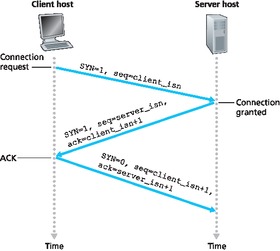
图 3.39 TCP 三次握手:报文段交换
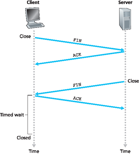
图 3.40 关闭 TCP 连接
天下无不散之筵席,TCP 连接也不例外。参与 TCP 连接的任一进程都可以结束连接。连接结束时,主机中的“资源”(即缓冲区和变量)将被释放。举例来说,假设客户端决定关闭连接,如 图3.40 所示。客户端应用进程发出关闭命令,这导致客户端 TCP 向服务器进程发送一个特殊 TCP 报文段。该报文段头部有一个标志位 FIN 位(见 图3.29)被置为1。当服务器收到该报文段时,会向客户端发送确认报文段。随后,服务器发送自己的关闭报文段,该报文段的 FIN 位也被置为1。最后,客户端确认服务器的关闭报文段。至此,双方主机中的所有资源都被释放。
在 TCP 连接生命周期内,每个主机运行的 TCP 协议都会经历各种 TCP 状态 的转换。图3.41 展示了客户端 TCP 典型的状态序列。客户端 TCP 从 CLOSED 状态开始。客户端应用程序发起新的 TCP 连接(在我们的 Java 示例以及 第2章 的 Python 示例中,是通过创建 Socket 对象实现的)。这导致客户端 TCP 向服务器 TCP 发送 SYN 报文段。发送 SYN 报文段后,客户端 TCP 进入 SYN_SENT 状态。在 SYN_SENT 状态,客户端 TCP 等待来自服务器 TCP 的报文段,该报文段包含对客户端之前报文段的确认且 SYN 位为1。收到此报文段后,客户端 TCP 进入 ESTABLISHED 状态。在 ESTABLISHED 状态,TCP 客户端可以发送和接收包含负载(即应用生成)数据的 TCP 报文段。
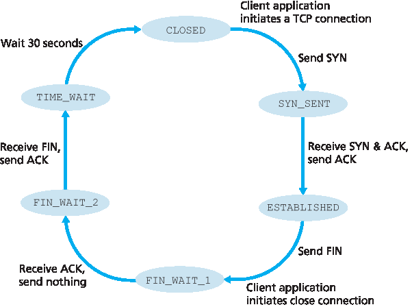
图 3.41 客户端 TCP 典型的状态序列
假设客户端应用决定关闭连接。(服务器也可选择关闭连接。)这导致客户端 TCP 发送一个 FIN 位为1的 TCP 报文段,并进入 FIN_WAIT_1 状态。在 FIN_WAIT_1 状态,客户端 TCP 等待服务器发送带有确认的 TCP 报文段。收到此报文段后,客户端 TCP 进入 FIN_WAIT_2 状态。在 FIN_WAIT_2 状态,客户端等待服务器发送另一个 FIN 位为1的报文段;收到该报文段后,客户端 TCP 确认服务器的报文段并进入 TIME_WAIT 状态。TIME_WAIT 状态允许 TCP 客户端重发最后的确认,以防确认丢失。TIME_WAIT 状态的持续时间依实现而异,典型值有 30 秒、1 分钟和 2 分钟。等待结束后,连接正式关闭,客户端所有资源(包括端口号)被释放。
图3.42 展示了假设客户端开始拆除连接时服务器端 TCP 通常经过的状态序列。状态转换图自解释。在这两个状态转换图中,我们只展示了 TCP 连接正常建立和关闭的过程,没有描述某些异常场景,例如双方同时想要发起或关闭连接的情况。如果你有兴趣了解这类和其他高级 TCP 议题,推荐参考 Stevens 的经典著作 [Stevens 1994]。
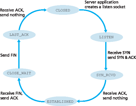
图 3.42 服务器端 TCP 典型状态序列
上述讨论假设客户端和服务器均准备通信,即服务器正在监听客户端发送 SYN 报文段的端口。现在考虑当主机收到的 TCP 报文段的端口号或源 IP 地址与主机上任何正在使用的套接字不匹配时会发生什么。例如,假设主机收到一个目标端口为 80 的 TCP SYN 报文段,但主机不接受端口 80 的连接(即没有运行 Web 服务器)。那么主机会向源地址发送一个特殊的重置报文段。该 TCP 报文段的 RST 标志位被置为 1(见 第3.5.2节)。因此,当主机发送重置报文段时,表示告诉源主机“我没有该报文段对应的套接字,请不要重发该报文段”。当主机收到目标端口号不匹配任何正在使用 UDP 套接字的 UDP 报文时,主机会发送一个特殊的 ICMP 数据报,如 第5章 所述。
既然我们已经很好地理解了 TCP 连接管理,接下来重新审视 nmap 端口扫描工具,仔细看看它如何工作。要探测目标主机的某个特定 TCP 端口(如端口 6789),nmap 会向该主机发送一个目标端口为 6789 的 TCP SYN 报文段。可能出现三种结果:
源主机收到目标主机发来的 TCP SYNACK 报文段。这意味着目标主机上在 TCP 端口 6789 运行着某个应用,nmap 返回“open”(开放)。
关注安全
SYN 洪泛攻击
我们在讨论 TCP 三次握手时看到,服务器在收到 SYN 后分配并初始化连接变量和缓冲区,然后发送 SYNACK 并等待客户端的 ACK 报文。如果客户端不发送完成三次握手第三步的 ACK,服务器最终(通常是一分钟或更长)会终止半开放连接并回收资源。
这种 TCP 连接管理协议为一种经典拒绝服务(DoS)攻击—— SYN 洪泛攻击 ——埋下伏笔。在此攻击中,攻击者大量发送 TCP SYN 报文段,但不完成三次握手的第三步。随着 SYN 报文段如洪水般涌入,服务器的连接资源被分配给大量半开放连接而耗尽(但未被使用!),合法客户端因此无法获得服务。SYN 洪泛攻击是最早被记录的 DoS 攻击之一 [CERT SYN 1996]。幸运的是,现在大多数主流操作系统都部署了有效防御措施——称为 SYN Cookies [RFC 4987]。SYN Cookies 工作原理如下:
当服务器收到 SYN 报文段时,不知道该报文是来自合法用户还是 SYN 洪泛攻击。因此,服务器不会为该 SYN 创建半开放 TCP 连接,而是创建一个初始 TCP 序列号,该序列号是一个复杂的函数(哈希函数),输入包括 SYN 报文段的源和目的 IP 地址及端口号,以及服务器私有的一个秘密数字。该精心构造的初始序列号即“cookie”。服务器随后用此特殊初始序列号发送 SYNACK 报文给客户端。重要的是,服务器不保存与该 SYN 对应的任何状态信息。
合法客户端会返回 ACK 报文。服务器收到该 ACK 后,必须验证其对应的是先前发送的 SYN。但服务器没有保存任何 SYN 状态信息,如何验证?如你所料,验证通过 cookie 实现。回想合法 ACK 的确认字段值应等于 SYNACK 中的初始序列号(即 cookie 值)加一(见 图3.39)。服务器使用相同哈希函数及 SYNACK 中的源、目的 IP 地址和端口号(与原 SYN 相同)及秘密数字计算结果,如果函数结果加一与客户端 ACK 中的确认值相同,服务器便认定该 ACK 对应先前的 SYN 并有效,然后创建完全打开的连接及套接字。
若客户端未返回 ACK 报文,则原始 SYN 对服务器无害,因为服务器尚未为该伪造 SYN 分配任何资源。
源主机收到目标主机发来的 TCP RST 报文段。这意味着 SYN 报文段抵达目标主机,但目标主机未在 TCP 端口 6789 上运行任何应用。但攻击者至少知道发送到该主机端口 6789 的报文未被路径中的防火墙阻断。(防火墙内容见 第8章。)
源主机未收到任何响应。这很可能意味着 SYN 报文段被中间防火墙阻断,未到达目标主机。
Nmap 是一个强大的工具,它不仅能探测开放的 TCP 端口,还能探测开放的 UDP 端口、防火墙及其配置,甚至应用程序和操作系统的版本。大部分功能是通过操作 TCP 连接管理报文实现的 [Skoudis 2006]。你可以从 www.nmap.org 下载 nmap。
至此,我们完成了对 TCP 错误控制和流量控制的介绍。在 第3.7节 中,我们将回到 TCP,深入探讨 TCP 拥塞控制。但在此之前,我们先退一步,从更广的角度考察拥塞控制问题。
In this subsection we take a closer look at how a TCP connection is established and torn down. Although this topic may not seem particularly thrilling, it is important because TCP connection establishment can significantly add to perceived delays (for example, when surfing the Web). Furthermore, many of the most common network attacks—including the incredibly popular SYN flood attack—exploit vulnerabilities in TCP connection management. Let’s first take a look at how a TCP connection is established. Suppose a process running in one host (client) wants to initiate a connection with another process in another host (server). The client application process first informs the client TCP that it wants to establish a connection to a process in the server. The TCP in the client then proceeds to establish a TCP connection with the TCP in the server in the following manner:
Step 1. The client-side TCP first sends a special TCP segment to the server-side TCP. This special segment contains no application-layer data. But one of the flag bits in the segment’s header (see Figure 3.29), the SYN bit, is set to 1. For this reason, this special segment is referred to as a SYN segment. In addition, the client randomly chooses an initial sequence number (
client_isn) and puts this number in the sequence number field of the initial TCP SYN segment. This segment is encapsulated within an IP datagram and sent to the server. There has been considerable interest in
properly randomizing the choice of the client_isn in order to avoid certain security attacks [CERT 2001–09].
- Step 2. Once the IP datagram containing the TCP SYN segment arrives at the server host (assuming it does arrive!), the server extracts the TCP SYN segment from the datagram, allocates the TCP buffers and variables to the connection, and sends a connection-granted segment to the client TCP. (We’ll see in Chapter 8 that the allocation of these buffers and variables before completing the third step of the three-way handshake makes TCP vulnerable to a denial-of-service attack known as SYN flooding.) This connection-granted segment also contains no application-layer data. However, it does contain three important pieces of information in the segment header. First, the SYN bit is set to 1. Second, the acknowledgment field of the TCP segment header is set to client_isn+1. Finally, the server chooses its own initial sequence number (server_isn) and puts this value in the sequence number field of the TCP segment header. This connection-granted segment is saying, in effect, “I received your SYN packet to start a connection with your initial sequence number, client_isn. I agree to establish this connection. My own initial sequence number is server_isn.” The connection-granted segment is referred to as a SYNACK segment.
- Step 3. Upon receiving the SYNACK segment, the client also allocates buffers and variables to the connection. The client host then sends the server yet another segment; this last segment acknowledges the server’s connection-granted segment (the client does so by putting the value server_isn+1 in the acknowledgment field of the TCP segment header). The SYN bit is set to zero, since the connection is established. This third stage of the three-way handshake may carry client-to-server data in the segment payload.
Once these three steps have been completed, the client and server hosts can send segments containing data to each other. In each of these future segments, the SYN bit will be set to zero. Note that in order to establish the connection, three packets are sent between the two hosts, as illustrated in Figure 3.39. For this reason, this connection-establishment procedure is often referred to as a three- way handshake. Several aspects of the TCP three-way handshake are explored in the homework problems (Why are initial sequence numbers needed? Why is a three-way handshake, as opposed to a two-way handshake, needed?). It’s interesting to note that a rock climber and a belayer (who is stationed below the rock climber and whose job it is to handle the climber’s safety rope) use a three- way-handshake communication protocol that is identical to TCP’s to ensure that both sides are ready before the climber begins ascent.
Figure 3.39 TCP three-way handshake: segment exchange
Figure 3.40 Closing a TCP connection
All good things must come to an end, and the same is true with a TCP connection. Either of the two processes participating in a TCP connection can end the connection. When a connection ends, the “resources” (that is, the buffers and variables) in the hosts are deallocated. As an example, suppose the client decides to close the connection, as shown in Figure 3.40. The client application process issues a close command. This causes the client TCP to send a special TCP segment to the server process. This special segment has a flag bit in the segment’s header, the FIN bit (see Figure 3.29), set to 1. When the server receives this segment, it sends the client an acknowledgment segment in return. The server then sends its own shutdown segment, which has the FIN bit set to 1. Finally, the client acknowledges the server’s shutdown segment. At this point, all the resources in the two hosts are now deallocated.
During the life of a TCP connection, the TCP protocol running in each host makes transitions through various TCP states. Figure 3.41 illustrates a typical sequence of TCP states that are visited by the client TCP. The client TCP begins in the CLOSED state. The application on the client side initiates a new TCP connection (by creating a Socket object in our Java examples as in the Python examples from Chapter 2). This causes TCP in the client to send a SYN segment to TCP in the server. After having sent the SYN segment, the client TCP enters the SYN_SENT state. While in the SYN_SENT state, the client TCP waits for a segment from the server TCP that includes an acknowledgment for the client’s previous segment and has the SYN bit set to 1. Having received such a segment, the client TCP enters the ESTABLISHED state. While in the ESTABLISHED state, the TCP client can send and receive TCP segments containing payload (that is, application-generated) data.
Figure 3.41 A typical sequence of TCP states visited by a client TCP
Suppose that the client application decides it wants to close the connection. (Note that the server could also choose to close the connection.) This causes the client TCP to send a TCP segment with the FIN bit set to 1 and to enter the FIN_WAIT_1 state. While in the FIN_WAIT_1 state, the client TCP waits for a TCP segment from the server with an acknowledgment. When it receives this segment, the client TCP enters the FIN_WAIT_2 state. While in the FIN_WAIT_2 state, the client waits for another segment from the server with the FIN bit set to 1; after receiving this segment, the client TCP acknowledges the server’s segment and enters the TIME_WAIT state. The TIME_WAIT state lets the TCP client resend the final acknowledgment in case the ACK is lost. The time spent in the TIME_WAIT state is implementation-dependent, but typical values are 30 seconds, 1 minute, and 2 minutes. After the wait, the connection formally closes and all resources on the client side (including port numbers) are released.
Figure 3.42 illustrates the series of states typically visited by the server-side TCP, assuming the client begins connection teardown. The transitions are self-explanatory. In these two state-transition diagrams, we have only shown how a TCP connection is normally established and shut down. We have not described what happens in certain pathological scenarios, for example, when both sides of a connection want to initiate or shut down at the same time. If you are interested in learning about this and other advanced issues concerning TCP, you are encouraged to see Stevens’ comprehensive book [Stevens 1994].
Figure 3.42 A typical sequence of TCP states visited by a server-side TCP
Our discussion above has assumed that both the client and server are prepared to communicate, i.e., that the server is listening on the port to which the client sends its SYN segment. Let’s consider what happens when a host receives a TCP segment whose port numbers or source IP address do not match with any of the ongoing sockets in the host. For example, suppose a host receives a TCP SYN packet with destination port 80, but the host is not accepting connections on port 80 (that is, it is not running a Web server on port 80). Then the host will send a special reset segment to the source. This TCP segment has the RST flag bit (see Section 3.5.2) set to 1. Thus, when a host sends a reset segment, it is telling the source “I don’t have a socket for that segment. Please do not resend the segment.” When a host receives a UDP packet whose destination port number doesn’t match with an ongoing UDP socket, the host sends a special ICMP datagram, as discussed in Chapter 5.
Now that we have a good understanding of TCP connection management, let’s revisit the nmap port- scanning tool and examine more closely how it works. To explore a specific TCP port, say port 6789, on a target host, nmap will send a TCP SYN segment with destination port 6789 to that host. There are three possible outcomes:
The source host receives a TCP SYNACK segment from the target host. Since this means that an application is running with TCP port 6789 on the target post, nmap returns “open.”
FOCUS ON SECURITY
The Syn Flood Attack
We’ve seen in our discussion of TCP’s three-way handshake that a server allocates and initializes connection variables and buffers in response to a received SYN. The server then sends a SYNACK in response, and awaits an ACK segment from the client. If the client does not send an ACK to complete the third step of this 3-way handshake, eventually (often after a minute or more) the server will terminate the half-open connection and reclaim the allocated resources.
This TCP connection management protocol sets the stage for a classic Denial of Service (DoS) attack known as the SYN flood attack. In this attack, the attacker(s) send a large number of TCP SYN segments, without completing the third handshake step. With this deluge of SYN segments, the server’s connection resources become exhausted as they are allocated (but never used!) for half-open connections; legitimate clients are then denied service. Such SYN flooding attacks were among the first documented DoS attacks [CERT SYN 1996]. Fortunately, an effective defense known as SYN cookies [RFC 4987] are now deployed in most major operating systems. SYN cookies work as follows:
When the server receives a SYN segment, it does not know if the segment is coming from a legitimate user or is part of a SYN flood attack. So, instead of creating a half-open TCP connection for this SYN, the server creates an initial TCP sequence number that is a complicated function (hash function) of source and destination IP addresses and port numbers of the SYN segment, as well as a secret number only known to the server. This carefully crafted initial sequence number is the so-called “cookie.” The server then sends the client a SYNACK packet with this special initial sequence number. Importantly, the server does not remember the cookie or any other state information corresponding to the SYN.
A legitimate client will return an ACK segment. When the server receives this ACK, it must verify that the ACK corresponds to some SYN sent earlier. But how is this done if the server maintains no memory about SYN segments? As you may have guessed, it is done with the cookie. Recall that for a legitimate ACK, the value in the acknowledgment field is equal to the initial sequence number in the SYNACK (the cookie value in this case) plus one (see Figure 3.39). The server can then run the same hash function using the source and destination IP address and port numbers in the SYNACK (which are the same as in the original SYN) and the secret number. If the result of the function plus one is the same as the acknowledgment (cookie) value in the client’s SYNACK, the server concludes that the ACK corresponds to an earlier SYN segment and is hence valid. The server then creates a fully open connection along with a socket.
On the other hand, if the client does not return an ACK segment, then the original SYN has done no harm at the server, since the server hasn’t yet allocated any resources in response to the original bogus SYN.
The source host receives a TCP RST segment from the target host. This means that the SYN segment reached the target host, but the target host is not running an application with TCP port 6789. But the attacker at least knows that the segments destined to the host at port 6789 are not blocked by any firewall on the path between source and target hosts. (Firewalls are discussed in Chapter 8.)
The source receives nothing. This likely means that the SYN segment was blocked by an intervening firewall and never reached the target host.
Nmap is a powerful tool that can “case the joint” not only for open TCP ports, but also for open UDP ports, for firewalls and their configurations, and even for the versions of applications and operating systems. Most of this is done by manipulating TCP connection-management segments [Skoudis 2006]. You can download nmap from www.nmap.org.
This completes our introduction to error control and flow control in TCP. In Section 3.7 we’ll return to TCP and look at TCP congestion control in some depth. Before doing so, however, we first step back and examine congestion-control issues in a broader context.