5.1 引言#
5.1 Introduction
让我们通过回顾 图 4.2 和 图 4.3 快速建立对网络控制平面的学习背景。在那里,我们看到转发表(在基于目的地的转发中)和流表(在广义转发中)是将网络层的数据平面和控制平面联系起来的主要元素。我们了解到,这些表指定了路由器在本地数据平面中的转发行为。我们还看到,在广义转发的情况下,所采取的操作(第 4.4.2 节)不仅可以是将数据包转发到路由器的输出端口,还可以是丢弃数据包、复制数据包,以及/或者重写第 2 层、第 3 层或第 4 层的包头字段。
在本章中,我们将学习这些转发表和流表是如何被计算、维护和安装的。在 第 4.1 节 中我们对网络层进行了介绍时,了解到可以通过两种方式实现上述目标:
每路由器控制。图 5.1 展示了这种情况下的情形,即每个路由器中都运行一个路由算法;转发功能和路由功能都包含在每个路由器中。每个路由器都包含一个路由组件,该组件与其他路由器中的路由组件通信,以计算其转发表的内容。这种每路由器控制的方法在互联网中已使用数十年。我们将在 第 5.3 节 和 第 5.4 节 中学习的 OSPF 和 BGP 协议就是基于这种每路由器控制的方法。
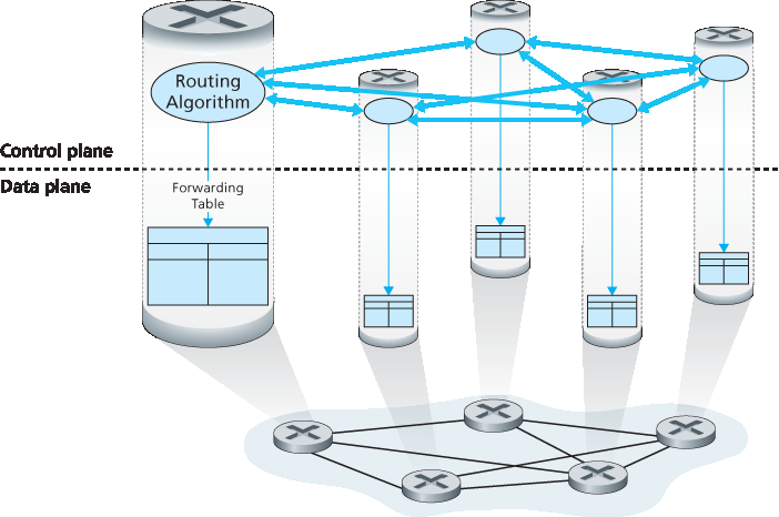
图 5.1 每路由器控制:各个路由算法组件在控制平面中进行交互
逻辑集中控制。图 5.2 展示了另一种情形,即一个逻辑上集中的控制器负责计算并分发每个路由器应使用的转发表。如我们在 第 4.4 节 中所见,广义的匹配加动作抽象允许路由器不仅可以执行传统的 IP 转发,还可以执行其他许多功能(负载共享、防火墙、NAT),这些功能在过去通常由独立的中间设备实现。
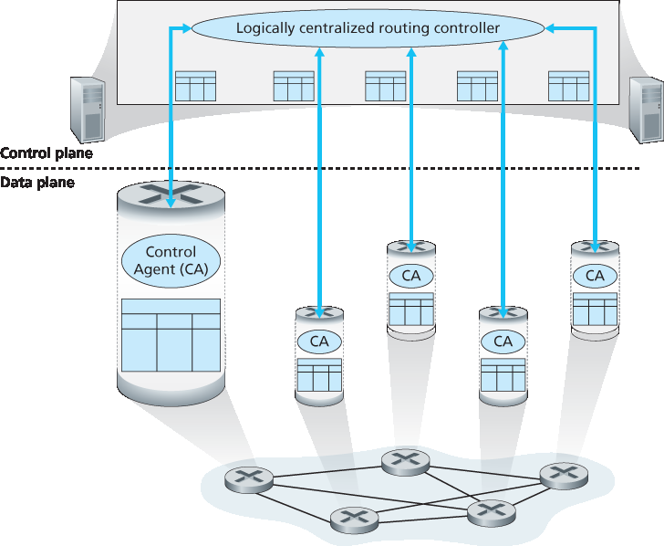
图 5.2 逻辑集中控制:一个独立的(通常是远程的)控制器与本地控制代理(CA)交互
控制器通过一个定义良好的协议与每个路由器中的控制代理(CA)进行交互,以配置和管理该路由器的流表。通常,CA 的功能非常有限;它的职责是与控制器通信,并按控制器的命令行事。不像 图 5.1 中的路由算法,CA 之间不会直接相互交互,也不会主动参与转发表的计算。这是每路由器控制与逻辑集中控制之间的一个关键区别。
“逻辑集中”控制 [Levin 2012] 意味着路由控制服务作为一个统一的中央服务点被访问,尽管该服务很可能为了容错性和性能可扩展性而由多个服务器实现。正如我们将在第 5.5 节中看到的,SDN 采用了这种逻辑集中的控制器概念——这是一种在生产部署中越来越常见的方法。Google 使用 SDN 来控制其内部 B4 全球广域网中互联数据中心的路由器 [Jain 2013]。微软研究院的 SWAN 系统 [Hong 2013] 使用逻辑集中控制器来管理广域网与数据中心网络之间的路由和转发。中国电信和中国联通都在数据中心内部以及数据中心之间使用 SDN [Li 2015]。AT&T 表示 [AT&T 2013] 它“支持许多 SDN 能力以及独立定义的、属于 SDN 架构框架的专有机制。”
Let’s quickly set the context for our study of the network control plane by recalling Figures 4.2 and 4.3. There, we saw that the forwarding table (in the case of destination-based forwarding) and the flow table (in the case of generalized forwarding) were the principal elements that linked the network layer’s data and control planes. We learned that these tables specify the local data-plane forwarding behavior of a router. We saw that in the case of generalized forwarding, the actions taken (Section 4.4.2) could include not only forwarding a packet to a router’s output port, but also dropping a packet, replicating a packet, and/or rewriting layer 2, 3 or 4 packet-header fields.
In this chapter, we’ll study how those forwarding and flow tables are computed, maintained and installed. In our introduction to the network layer in Section 4.1, we learned that there are two possible approaches for doing so.
Per-router control. Figure 5.1 illustrates the case where a routing algorithm runs in each and every router; both a forwarding and a routing function are contained within each router. Each router has a routing component that communicates with the routing components in other routers to compute the values for its forwarding table. This per-router control approach has been used in the Internet for decades. The OSPF and BGP protocols that we’ll study in Sections 5.3 and 5.4 are based on this per-router approach to control.
Figure 5.1 Per-router control: Individual routing algorithm components interact in the control plane
Logically centralized control. Figure 5.2 illustrates the case in which a logically centralized controller computes and distributes the forwarding tables to be used by each and every router. As we saw in Section 4.4, the generalized match-plus-action abstraction allows the router to perform traditional IP forwarding as well as a rich set of other functions (load sharing, firewalling, and NAT) that had been previously implemented in separate middleboxes.
Figure 5.2 Logically centralized control: A distinct, typically remote, controller interacts with local control agents (CAs)
The controller interacts with a control agent (CA) in each of the routers via a well-defined protocol to configure and manage that router’s flow table. Typically, the CA has minimum functionality; its job is to communicate with the controller, and to do as the controller commands. Unlike the routing algorithms in Figure 5.1, the CAs do not directly interact with each other nor do they actively take part in computing the forwarding table. This is a key distinction between per-router control and logically centralized control.
By “logically centralized” control [Levin 2012] we mean that the routing control service is accessed as if it were a single central service point, even though the service is likely to be implemented via multiple servers for fault-tolerance, and performance scalability reasons. As we will see in Section 5.5, SDN adopts this notion of a logically centralized controller—an approach that is finding increased use in production deployments. Google uses SDN to control the routers in its internal B4 global wide-area network that interconnects its data centers [Jain 2013]. SWAN [Hong 2013], from Microsoft Research, uses a logically centralized controller to manage routing and forwarding between a wide area network and a data center network. China Telecom and China Unicom are using SDN both within data centers and between data centers [Li 2015]. AT&T has noted [AT&T 2013] that it “supports many SDN capabilities and independently defined, proprietary mechanisms that fall under the SDN architectural framework.”