6.7 回顾:网页请求生命周期中的一天#
6.7 Retrospective: A Day in the Life of a Web Page Request
现在我们已经在本章中介绍了链路层,并在前几章中介绍了网络层、传输层和应用层,我们对协议栈的探索也就此完成!在本书的最开始(第 1.1 节),我们写道“本书的大部分内容涉及计算机网络协议”,在前五章中我们确实已经看到了这一点!在进入本书第二部分的专题章节之前,我们希望通过一种整合性的、整体性的视角对我们迄今为止学习过的协议进行总结。我们可以通过分析一个最简单的请求——下载一个网页——来获得这种“全局视角”,并识别出在满足这个简单请求时涉及的众多(非常多!)协议。图 6.32 展示了我们的场景:学生 Bob 将笔记本连接到他学校的以太网交换机,并下载一个网页(例如 www.google.com 的首页)。正如我们现在所知道的,实现这个看似简单的请求实际上在“幕后”发生了很多事情。本章最后的 Wireshark 实验将更详细地检查包含多个相关数据包的跟踪文件。
Now that we’ve covered the link layer in this chapter, and the network, transport and application layers in earlier chapters, our journey down the protocol stack is complete! In the very beginning of this book (Section 1.1), we wrote “much of this book is concerned with computer network protocols,” and in the first five chapters, we’ve certainly seen that this is indeed the case! Before heading into the topical chapters in second part of this book, we’d like to wrap up our journey down the protocol stack by taking an integrated, holistic view of the protocols we’ve learned about so far. One way then to take this “big picture” view is to identify the many (many!) protocols that are involved in satisfying even the simplest request: downloading a Web page. Figure 6.32 illustrates our setting: a student, Bob, connects a laptop to his school’s Ethernet switch and downloads a Web page (say the home page of www.google.com). As we now know, there’s a lot going on “under the hood” to satisfy this seemingly simple request. A Wireshark lab at the end of this chapter examines trace files containing a number of the packets involved in similar scenarios in more detail.
6.7.1 开始:DHCP、UDP、IP 和以太网#
6.7.1 Getting Started: DHCP, UDP, IP, and Ethernet
假设 Bob 启动了他的笔记本电脑,然后将其连接到连接到学校以太网交换机的以太网电缆上,该交换机又连接到学校的路由器,如 图 6.32 所示。学校的路由器连接到 ISP,在本例中是 comcast.net。在这个例子中,comcast.net 为学校提供 DNS 服务;因此,DNS 服务器位于 Comcast 网络中而不是学校网络中。我们假设 DHCP 服务器运行在路由器中,这在实际中也很常见。
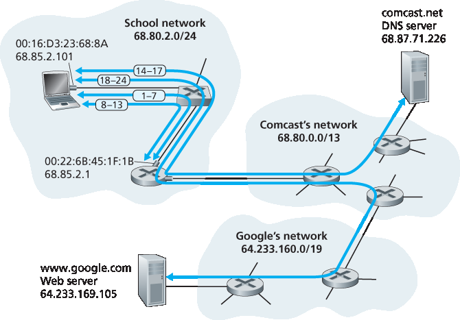
图 6.32 网页请求的一天:网络设置与动作
当 Bob 第一次将笔记本连接到网络时,在没有 IP 地址的情况下他无法进行任何操作(例如下载网页)。因此,Bob 的笔记本所进行的第一个与网络相关的操作是运行 DHCP 协议,以从本地 DHCP 服务器获取 IP 地址以及其他信息:
Bob 笔记本上的操作系统创建一个 DHCP 请求报文 (第 4.3.3 节),并将其封装在一个 UDP 段 (第 3.3 节)中,目标端口为 67(DHCP 服务器),源端口为 68(DHCP 客户端)。该 UDP 段被封装在一个 IP 数据报 (第 4.3.1 节)中,目标 IP 地址为广播地址 255.255.255.255,源 IP 地址为 0.0.0.0,因为 Bob 的笔记本尚未有 IP 地址。
包含 DHCP 请求报文的 IP 数据报被封装在一个 以太网帧 中(第 6.4.2 节)。该以太网帧的目标 MAC 地址为 FF:FF:FF:FF:FF:FF,从而使帧可以广播给连接到交换机的所有设备(希望包括 DHCP 服务器);帧的源 MAC 地址为 Bob 笔记本的地址,即 00:16:D3:23:68:8A。
包含 DHCP 请求的广播以太网帧是 Bob 的笔记本发送到以太网交换机的第一个帧。交换机将收到的帧广播到所有输出端口,包括连接到路由器的端口。
路由器在其 MAC 地址为 00:22:6B:45:1F:1B 的接口上接收到包含 DHCP 请求的广播以太网帧,并从中提取 IP 数据报。该数据报的广播 IP 目的地址表明该数据报应该由该节点的上层协议处理,因此数据报的有效载荷(UDP 段)被 多路分解 到 UDP 层(第 3.2 节),并从中提取 DHCP 请求报文。此时 DHCP 服务器接收到 DHCP 请求报文。
假设运行在路由器中的 DHCP 服务器可以在 CIDR (第 4.3.3 节)地址块 68.85.2.0/24 中分配 IP 地址。在这个例子中,学校中使用的所有 IP 地址都属于 Comcast 的地址块。假设 DHCP 服务器分配了地址 68.85.2.101 给 Bob 的笔记本。DHCP 服务器创建一个 DHCP ACK 报文 (第 4.3.3 节),其中包含该 IP 地址、DNS 服务器的 IP 地址(68.87.71.226)、默认网关路由器的 IP 地址(68.85.2.1)以及子网块(68.85.2.0/24)(等价于“网络掩码”)。DHCP 报文被封装在 UDP 段中,再封装在 IP 数据报中,最后封装在以太网帧中。以太网帧的源 MAC 地址为路由器家庭网络接口的地址(00:22:6B:45:1F:1B),目标 MAC 地址为 Bob 笔记本的地址(00:16:D3:23:68:8A)。
包含 DHCP ACK 的以太网帧由路由器单播发送给交换机。由于交换机是自学习的(第 6.4.3 节),并且之前接收到了来自 Bob 笔记本的包含 DHCP 请求的以太网帧,因此交换机知道只将发送给地址为 00:16:D3:23:68:8A 的帧转发到通向 Bob 笔记本的输出端口。
Bob 的笔记本接收到包含 DHCP ACK 的以太网帧,从中提取 IP 数据报,再从中提取 UDP 段,最后从中提取 DHCP ACK 报文。Bob 的 DHCP 客户端随后记录其 IP 地址和 DNS 服务器的 IP 地址,并将默认网关的地址安装到其 IP 转发表 中(第 4.1 节)。Bob 的笔记本将所有目标地址不在其子网 68.85.2.0/24 内的数据报发送至默认网关。此时,Bob 的笔记本已初始化其网络组件,准备开始处理网页获取请求。(注意,第 4 章 中呈现的四个 DHCP 步骤中,实际上只需要最后两个步骤。)
Let’s suppose that Bob boots up his laptop and then connects it to an Ethernet cable connected to the school’s Ethernet switch, which in turn is connected to the school’s router, as shown in Figure 6.32. The school’s router is connected to an ISP, in this example, comcast.net. In this example, comcast.net is providing the DNS service for the school; thus, the DNS server resides in the Comcast network rather than the school network. We’ll assume that the DHCP server is running within the router, as is often the case.
Figure 6.32 A day in the life of a Web page request: Network setting and actions
When Bob first connects his laptop to the network, he can’t do anything (e.g., download a Web page) without an IP address. Thus, the first network-related action taken by Bob’s laptop is to run the DHCP protocol to obtain an IP address, as well as other information, from the local DHCP server:
The operating system on Bob’s laptop creates a DHCP request message (Section 4.3.3) and puts this message within a UDP segment (Section 3.3) with destination port 67 (DHCP server) and source port 68 (DHCP client). The UDP segment is then placed within an IP datagram (Section 4.3.1) with a broadcast IP destination address (255.255.255.255) and a source IP address of 0.0.0.0, since Bob’s laptop doesn’t yet have an IP address.
The IP datagram containing the DHCP request message is then placed within an Ethernet frame (Section 6.4.2). The Ethernet frame has a destination MAC addresses of FF:FF:FF:FF:FF:FF so that the frame will be broadcast to all devices connected to the switch (hopefully including a DHCP server); the frame’s source MAC address is that of Bob’s laptop, 00:16:D3:23:68:8A.
The broadcast Ethernet frame containing the DHCP request is the first frame sent by Bob’s laptop to the Ethernet switch. The switch broadcasts the incoming frame on all outgoing ports, including the port connected to the router.
The router receives the broadcast Ethernet frame containing the DHCP request on its interface with MAC address 00:22:6B:45:1F:1B and the IP datagram is extracted from the Ethernet frame. The datagram’s broadcast IP destination address indicates that this IP datagram should be processed by upper layer protocols at this node, so the datagram’s payload (a UDP segment) is thus demultiplexed (Section 3.2) up to UDP, and the DHCP request message is extracted from the UDP segment. The DHCP server now has the DHCP request message.
5. Let’s suppose that the DHCP server running within the router can allocate IP addresses in the CIDR (Section 4.3.3) block 68.85.2.0/24. In this example, all IP addresses used within the school are thus within Comcast’s address block. Let’s suppose the DHCP server allocates address 68.85.2.101 to Bob’s laptop. The DHCP server creates a DHCP ACK message (Section 4.3.3) containing this IP address, as well as the IP address of the DNS server (68.87.71.226), the IP address for the default gateway router (68.85.2.1), and the subnet block (68.85.2.0/24) (equivalently, the “network mask”). The DHCP message is put inside a UDP segment, which is put inside an IP datagram, which is put inside an Ethernet frame. The Ethernet frame has a source MAC address of the router’s interface to the home network (00:22:6B:45:1F:1B) and a destination MAC address of Bob’s laptop (00:16:D3:23:68:8A). 6. The Ethernet frame containing the DHCP ACK is sent (unicast) by the router to the switch. Because the switch is self-learning (Section 6.4.3) and previously received an Ethernet frame (containing the DHCP request) from Bob’s laptop, the switch knows to forward a frame addressed to 00:16:D3:23:68:8A only to the output port leading to Bob’s laptop. 7. Bob’s laptop receives the Ethernet frame containing the DHCP ACK, extracts the IP datagram from the Ethernet frame, extracts the UDP segment from the IP datagram, and extracts the DHCP ACK message from the UDP segment. Bob’s DHCP client then records its IP address and the IP address of its DNS server. It also installs the address of the default gateway into its IP forwarding table (Section 4.1). Bob’s laptop will send all datagrams with destination address outside of its subnet 68.85.2.0/24 to the default gateway. At this point, Bob’s laptop has initialized its networking components and is ready to begin processing the Web page fetch. (Note that only the last two DHCP steps of the four presented in Chapter 4 are actually necessary.)
6.7.2 仍在开始阶段:DNS 和 ARP#
6.7.2 Still Getting Started: DNS and ARP
当 Bob 在他的网页浏览器中输入 www.google.com 的 URL 时,他启动了一连串最终会导致谷歌主页显示在浏览器上的操作。Bob 的网页浏览器首先创建一个将用于发送 HTTP 请求 (第 2.2 节)到 www.google.com 的 TCP 套接字 (第 2.7 节)。为了创建这个套接字,Bob 的笔记本需要知道 www.google.com 的 IP 地址。正如我们在 第 2.5 节 中所学到的, DNS 协议 被用来提供这种从名称到 IP 地址的转换服务。
因此,Bob 的笔记本操作系统创建一个 DNS 查询报文 (第 2.5.3 节),并将字符串 “www.google.com” 放入该 DNS 报文的问题部分中。该 DNS 报文随后被封装在一个 UDP 段中,目标端口为 53(DNS 服务器)。该 UDP 段被封装在一个 IP 数据报中,其目标 IP 地址为 68.87.71.226(在第 5 步中 DHCP ACK 返回的 DNS 服务器地址),源 IP 地址为 68.85.2.101。
然后 Bob 的笔记本将包含 DNS 查询报文的数据报封装在一个以太网帧中。该帧将被发送(在链路层中定址)到 Bob 学校网络中的网关路由器。然而,尽管 Bob 的笔记本通过上面的第 5 步中的 DHCP ACK 报文知道了学校网关路由器的 IP 地址(68.85.2.1),但它并不知道该路由器的 MAC 地址。为了获取网关路由器的 MAC 地址,Bob 的笔记本需要使用 ARP 协议(第 6.4.1 节)。
Bob 的笔记本创建一个目标 IP 地址为 68.85.2.1(默认网关)的 ARP 查询报文,将该 ARP 报文封装在一个目标地址为广播地址(FF:FF:FF:FF:FF:FF)的以太网帧中,并将该帧发送到交换机,交换机将帧转发给所有连接的设备,包括网关路由器。
网关路由器在连接到学校网络的接口上接收到包含 ARP 查询报文的帧,并发现 ARP 报文中的目标 IP 地址 68.85.2.1 与其接口的 IP 地址匹配。因此,网关路由器准备一个 ARP 响应报文,表明其 MAC 地址 00:22:6B:45:1F:1B 对应于 IP 地址 68.85.2.1。它将 ARP 响应报文封装在一个以太网帧中,目标地址为 00:16:D3:23:68:8A(Bob 的笔记本),并将帧发送到交换机,交换机将帧转发给 Bob 的笔记本。
Bob 的笔记本接收到包含 ARP 响应报文的帧,并从该报文中提取出网关路由器的 MAC 地址(00:22:6B:45:1F:1B)。
Bob 的笔记本现在(终于!)可以将包含 DNS 查询报文的以太网帧定址给网关路由器的 MAC 地址。请注意,该帧中的 IP 数据报的目的地址是 68.87.71.226(DNS 服务器),而帧的目的地址是 00:22:6B:45:1F:1B(网关路由器)。Bob 的笔记本将该帧发送到交换机,交换机将其转发给网关路由器。
When Bob types the URL for www.google.com into his Web browser, he begins the long chain of events that will eventually result in Google’s home page being displayed by his Web browser. Bob’s Web browser begins the process by creating a TCP socket (Section 2.7) that will be used to send the HTTP request (Section 2.2) to www.google.com. In order to create the socket, Bob’s laptop will need to know the IP address of www.google.com. We learned in Section 2.5, that the DNS protocol is used to provide this name-to-IP-address translation service.
The operating system on Bob’s laptop thus creates a DNS query message (Section 2.5.3), putting the string “www.google.com” in the question section of the DNS message. This DNS message is then placed within a UDP segment with a destination port of 53 (DNS server). The UDP segment is then placed within an IP datagram with an IP destination address of 68.87.71.226 (the address of the DNS server returned in the DHCP ACK in step 5) and a source IP address of 68.85.2.101.
Bob’s laptop then places the datagram containing the DNS query message in an Ethernet frame. This frame will be sent (addressed, at the link layer) to the gateway router in Bob’s school’s network. However, even though Bob’s laptop knows the IP address of the school’s gateway router (68.85.2.1) via the DHCP ACK message in step 5 above, it doesn’t know the gateway router’s MAC address. In order to obtain the MAC address of the gateway router, Bob’s laptop will need to use the ARP protocol (Section 6.4.1).
3. Bob’s laptop creates an ARP query message with a target IP address of 68.85.2.1 (the default gateway), places the ARP message within an Ethernet frame with a broadcast destination address (FF:FF:FF:FF:FF:FF) and sends the Ethernet frame to the switch, which delivers the frame to all connected devices, including the gateway router. 1. The gateway router receives the frame containing the ARP query message on the interface to the school network, and finds that the target IP address of 68.85.2.1 in the ARP message matches the IP address of its interface. The gateway router thus prepares an ARP reply, indicating that its MAC address of 00:22:6B:45:1F:1B corresponds to IP address 68.85.2.1. It places the ARP reply message in an Ethernet frame, with a destination address of 00:16:D3:23:68:8A (Bob’s laptop) and sends the frame to the switch, which delivers the frame to Bob’s laptop. 2. Bob’s laptop receives the frame containing the ARP reply message and extracts the MAC address of the gateway router (00:22:6B:45:1F:1B) from the ARP reply message. 3. Bob’s laptop can now (finally!) address the Ethernet frame containing the DNS query to the gateway router’s MAC address. Note that the IP datagram in this frame has an IP destination address of 68.87.71.226 (the DNS server), while the frame has a destination address of 00:22:6B:45:1F:1B (the gateway router). Bob’s laptop sends this frame to the switch, which delivers the frame to the gateway router.
6.7.3 仍在开始阶段:到 DNS 服务器的域内路由#
6.7.3 Still Getting Started: Intra-Domain Routing to the DNS Server
网关路由器接收到该帧并提取出包含 DNS 查询报文的 IP 数据报。路由器查阅该数据报的目的地址(68.87.71.226),并根据其转发表确定该数据报应被发送至 图 6.32 中 Comcast 网络中最左侧的路由器。IP 数据报被封装在适用于学校路由器与 Comcast 最左侧路由器之间链路的链路层帧中,并通过该链路发送。
Comcast 网络中最左侧的路由器接收到该帧,提取出 IP 数据报,检查其目的地址(68.87.71.226),并根据其由 Comcast 的域内协议(如 RIP、 OSPF 或 IS-IS,第 5.3 节)以及 Internet 域间协议 BGP (第 5.4 节)填充的转发表确定转发数据报至 DNS 服务器的出接口。
最终,包含 DNS 查询的 IP 数据报抵达 DNS 服务器。DNS 服务器从中提取出 DNS 查询报文,查找其 DNS 数据库中的 www.google.com( 第 2.4 节 ),并找到包含 www.google.com 的 IP 地址(64.233.169.105)的 DNS 资源记录 (假设该记录当前已被缓存)。请回忆,这个缓存数据最初来源于 googlecom 的 权威 DNS 服务器 ( 第 2.4.2 节 )。DNS 服务器构建一个包含主机名到 IP 地址映射的 DNS 响应报文,将该 DNS 响应封装在 UDP 段中,并将该段封装在一个目的地址为 Bob 笔记本(68.85.2.101)的 IP 数据报中。该数据报将经由 Comcast 网络转发回学校的路由器,并最终通过以太网交换机转发至 Bob 的笔记本。
Bob 的笔记本从该 DNS 报文中提取出 www.google.com 的 IP 地址。经过大量工作之后,Bob 的笔记本终于可以开始访问 www.google.com 服务器了!
The gateway router receives the frame and extracts the IP datagram containing the DNS query. The router looks up the destination address of this datagram (68.87.71.226) and determines from its forwarding table that the datagram should be sent to the leftmost router in the Comcast network in Figure 6.32. The IP datagram is placed inside a link-layer frame appropriate for the link connecting the school’s router to the leftmost Comcast router and the frame is sent over this link.
The leftmost router in the Comcast network receives the frame, extracts the IP datagram, examines the datagram’s destination address (68.87.71.226) and determines the outgoing interface on which to forward the datagram toward the DNS server from its forwarding table, which has been filled in by Comcast’s intra-domain protocol (such as RIP, OSPF or IS-IS, Section 5.3) as well as the Internet’s inter-domain protocol, BGP (Section 5.4).
Eventually the IP datagram containing the DNS query arrives at the DNS server. The DNS server extracts the DNS query message, looks up the name www.google.com in its DNS database (Section 2.5), and finds the DNS resource record that contains the IP address (64.233.169.105) for www.google.com. (assuming that it is currently cached in the DNS server). Recall that this cached data originated in the authoritative DNS server (Section 2.5.2) for googlecom. The DNS server forms a DNS reply message containing this hostname-to-IP- address mapping, and places the DNS reply message in a UDP segment, and the segment within an IP datagram addressed to Bob’s laptop (68.85.2.101). This datagram will be forwarded back through the Comcast network to the school’s router and from there, via the Ethernet switch to Bob’s laptop.
Bob’s laptop extracts the IP address of the server www.google.com from the DNS message. Finally, after a lot of work, Bob’s laptop is now ready to contact the www.google.com server!
6.7.4 Web 客户端-服务器交互:TCP 与 HTTP#
6.7.4 Web Client-Server Interaction: TCP and HTTP
现在 Bob 的笔记本已经获得 www.google.com 的 IP 地址,它可以创建一个 TCP 套接字(第 2.7 节),用于向 www.google.com 发送 HTTP GET 报文(第 2.2.3 节)。在 Bob 创建 TCP 套接字时,其笔记本中的 TCP 模块首先必须与 www.google.com 的 TCP 模块完成三次握手(第 3.5.6 节)。因此,Bob 的笔记本首先创建一个目标端口为 80(HTTP)的 TCP SYN 段,将其封装在一个目的 IP 地址为 64.233.169.105(www.google.com)的 IP 数据报中,再将数据报封装在一个目的 MAC 地址为 00:22:6B:45:1F:1B(网关路由器)的帧中,并将该帧发送到交换机。
学校网络、Comcast 网络和 Google 网络中的路由器根据各自的转发表将包含 TCP SYN 的数据报转发至 www.google.com,如上述步骤 14–16 所示。请回忆,Comcast 与 Google 网络之间的域间链路的转发由 BGP 协议 (第 5 章)决定。
最终,包含 TCP SYN 的数据报抵达 www.google.com。TCP SYN 报文从数据报中提取并多路分解至与端口 80 相关联的欢迎套接字。为 Google HTTP 服务器与 Bob 笔记本之间的连接创建一个连接套接字(第 2.7 节)。然后生成一个 TCP SYNACK 段(第 3.5.6 节),封装在一个发往 Bob 笔记本的数据报中,最后封装在一个适合连接 www.google.com 与其第一跳路由器之间链路的链路层帧中。
包含 TCP SYNACK 段的数据报通过 Google、Comcast 和学校网络转发,最终抵达 Bob 笔记本中的以太网卡。数据报在操作系统中多路分解至第 18 步中创建的 TCP 套接字,该套接字进入连接状态。
现在 Bob 的笔记本上的套接字终于准备好向 www.google.com 发送字节了,Bob 的浏览器创建一个包含所要获取的 URL 的 HTTP GET 报文(第 2.2.3 节)。该 HTTP GET 报文被写入套接字,成为 TCP 段的有效载荷。TCP 段被封装在数据报中,并按步骤 18–20 中所述的方式发送并传送至 www.google.com。
www.google.com 上的 HTTP 服务器从 TCP 套接字中读取 HTTP GET 报文,创建一个 HTTP 响应报文 (第 2.2 节),将所请求的网页内容放入响应报文的主体中,并将该报文写入 TCP 套接字。
包含 HTTP 响应报文的数据报通过 Google、Comcast 和学校网络转发,最终抵达 Bob 的笔记本。Bob 的网页浏览器程序从套接字中读取 HTTP 响应,从响应主体中提取出网页的 HTML 内容,并最终(终于!)将网页显示出来!
我们上面的场景涵盖了大量的网络知识!如果你理解了上述示例的大部分甚至全部内容,那么自你第一次阅读 第 1.1 节 起你已经掌握了很多知识,当时我们写道“本书的大部分内容涉及计算机网络协议”,你也许还在疑惑什么是协议!尽管上述示例已经非常详尽,但我们仍省略了一些可能涉及的额外协议(例如运行在学校网关路由器中的 NAT、对学校网络的无线访问、访问学校网络或对段或数据报加密的安全协议、网络管理协议),以及在公共互联网中可能遇到的一些考量(网页缓存、DNS 层级结构)。我们将在本书的第二部分中涵盖这些话题及更多内容。
最后我们指出,以上的示例提供了一个集成且整体的,但也非常“零部件式”的视角,涵盖了我们在本书第一部分中学习的许多协议。这个示例更关注“怎么做”而非“为什么”。想要获得更广泛、更具反思性的网络协议设计视角,可参阅 [Clark 1988,RFC 5218]。
Now that Bob’s laptop has the IP address of www.google.com, it can create the TCP socket (Section 2.7) that will be used to send the HTTP GET message (Section 2.2.3) to www.google.com. When Bob creates the TCP socket, the TCP in Bob’s laptop must first perform a three-way handshake (Section 3.5.6) with the TCP in www.google.com. Bob’s laptop thus first creates a TCP SYN segment with destination port 80 (for HTTP), places the TCP segment inside an IP datagram with a destination IP address of 64.233.169.105 (www.google.com), places the datagram inside a frame with a destination MAC address of 00:22:6B:45:1F:1B (the gateway router) and sends the frame to the switch.
The routers in the school network, Comcast’s network, and Google’s network forward the datagram containing the TCP SYN toward www.google.com, using the forwarding table in each router, as in steps 14–16 above. Recall that the router forwarding table entries governing forwarding of packets over the inter-domain link between the Comcast and Google networks are determined by the BGP protocol (Chapter 5).
Eventually, the datagram containing the TCP SYN arrives at www.google.com. The TCP SYN message is extracted from the datagram and demultiplexed to the welcome socket associated with port 80. A connection socket (Section 2.7) is created for the TCP connection between the Google HTTP server and Bob’s laptop. A TCP SYNACK (Section 3.5.6) segment is generated, placed inside a datagram addressed to Bob’s laptop, and finally placed inside a link-layer frame appropriate for the link connecting www.google.com to its first-hop router.
The datagram containing the TCP SYNACK segment is forwarded through the Google, Comcast, and school networks, eventually arriving at the Ethernet card in Bob’s laptop. The datagram is demultiplexed within the operating system to the TCP socket created in step 18, which enters the connected state.
With the socket on Bob’s laptop now (finally!) ready to send bytes to www.google.com, Bob’s browser creates the HTTP GET message (Section 2.2.3) containing the URL to be fetched. The HTTP GET message is then written into the socket, with the GET message becoming the payload of a TCP segment. The TCP segment is placed in a datagram and sent and delivered to www.google.com as in steps 18–20 above.
The HTTP server at www.google.com reads the HTTP GET message from the TCP socket, creates an HTTP response message (Section 2.2), places the requested Web page content in the body of the HTTP response message, and sends the message into the TCP socket.
The datagram containing the HTTP reply message is forwarded through the Google, Comcast, and school networks, and arrives at Bob’s laptop. Bob’s Web browser program reads the HTTP response from the socket, extracts the html for the Web page from the body of the HTTP response, and finally (finally!) displays the Web page!
Our scenario above has covered a lot of networking ground! If you’ve understood most or all of the above example, then you’ve also covered a lot of ground since you first read Section 1.1, where we wrote “much of this book is concerned with computer network protocols” and you may have wondered what a protocol actually was! As detailed as the above example might seem, we’ve omitted a number of possible additional protocols (e.g., NAT running in the school’s gateway router, wireless access to the school’s network, security protocols for accessing the school network or encrypting segments or datagrams, network management protocols), and considerations (Web caching, the DNS hierarchy) that one would encounter in the public Internet. We’ll cover a number of these topics and more in the second part of this book.
Lastly, we note that our example above was an integrated and holistic, but also very “nuts and bolts,” view of many of the protocols that we’ve studied in the first part of this book. The example focused more on the “how” than the “why.” For a broader, more reflective view on the design of network protocols in general, see [Clark 1988, RFC 5218].