7.3 WiFi:802.11 无线局域网#
7.3 WiFi: 802.11 Wireless LANs
在办公场所、家庭、教育机构、咖啡馆、机场以及街角随处可见的无线局域网,如今已经成为互联网中最重要的接入网络技术之一。尽管在 1990 年代开发了多种无线局域网技术和标准,但有一类标准明显脱颖而出: IEEE 802.11 无线局域网,也称为 WiFi。在本节中,我们将深入了解 802.11 无线局域网,考察其帧结构、介质访问协议,以及 802.11 局域网与有线以太网局域网的互联方式。
IEEE 802.11(“WiFi”)系列中包含多个无线局域网技术标准,如 表 7.1 所示。这些不同的 802.11 标准都具有一些共同特征。它们都使用相同的介质访问协议 CSMA/CA,我们将在稍后讨论。三种标准在链路层帧中都使用相同的帧结构。这三种标准都可以降低其传输速率以延伸通信距离。重要的是,802.11 产品都是向后兼容的,例如,一个仅支持 802.11g 的移动设备仍然可以与更新的 802.11ac 基站通信。
然而,如 表 7.1 所示,这些标准在物理层上有一些主要差异。802.11 设备运行于两个不同的频率范围:2.4–2.485 GHz(称为 2.4 GHz 频段)和 5.1–5.8 GHz(称为 5 GHz 频段)。2.4 GHz 是一个无需许可的频段,在此频段内,802.11 设备可能与 2.4 GHz 电话和微波炉等设备争夺频谱资源。在 5 GHz 下,对于相同功率水平,802.11 局域网的传输距离更短,且多路径传播问题更严重。最新的两个标准 802.11n [IEEE 802.11n 2012] 和 802.11ac [IEEE 802.11ac 2013;Cisco 802.11ac 2015] 使用多输入多输出(MIMO)天线;即发送端和接收端均配有两个或多个用于传输/接收不同信号的天线 [Diggavi 2004]。802.11ac 基站可以同时向多个终端发送信号,并使用“智能”天线自适应波束成形技术,使信号朝向目标接收方向发送。这可以减少干扰并在一定数据速率下增加通信距离。表 7.1 中的数据速率是理想环境下的结果,例如接收器距离基站 1 米、无干扰的场景——这种情况在现实中几乎不会发生!所以常言道:YMMV(Your Mileage May Vary,意即你的无线数据速率可能会有所不同)。
表 7.1 IEEE 802.11 标准汇总
标准 |
频率范围 |
数据速率 |
802.11b |
2.4 GHz |
高达 11 Mbps |
802.11a |
5 GHz |
高达 54 Mbps |
802.11g |
2.4 GHz |
高达 54 Mbps |
802.11n |
2.5 GHz 和 5 GHz |
高达 450 Mbps |
802.11ac |
5 GHz |
高达 1300 Mbps |
Pervasive in the workplace, the home, educational institutions, cafés, airports, and street corners, wireless LANs are now one of the most important access network technologies in the Internet today. Although many technologies and standards for wireless LANs were developed in the 1990s, one particular class of standards has clearly emerged as the winner: the IEEE 802.11 wireless LAN, also known as WiFi. In this section, we’ll take a close look at 802.11 wireless LANs, examining its frame structure, its medium access protocol, and its internetworking of 802.11 LANs with wired Ethernet LANs.
There are several 802.11 standards for wireless LAN technology in the IEEE 802.11 (“WiFi”) family, as summarized in Table 7.1. The different 802.11 standards all share some common characteristics. They all use the same medium access protocol, CSMA/CA, which we’ll discuss shortly. All three use the same frame structure for their link-layer frames as well. All three standards have the ability to reduce their transmission rate in order to reach out over greater distances. And, importantly, 802.11 products are also all backwards compatible, meaning, for example, that a mobile capable only of 802.11g may still interact with a newer 802.11ac base station.
However, as shown in Table 7.1, the standards have some major differences at the physical layer. 802.11 devices operate in two difference frequency ranges: 2.4–2.485 GHz (referred to as the 2.4 GHz range) and 5.1 – 5.8 GHz (referred to as the 5 GHz range). The 2.4 GHz range is an unlicensed frequency band, where 802.11 devices may compete for frequency spectrum with 2.4 GHz phones and microwave ovens. At 5 GHz, 802.11 LANs have a shorter transmission distance for a given power level and suffer more from multipath propagation. The two most recent standards, 802.11n [IEEE 802.11n 2012] and 802.11ac [IEEE 802.11ac 2013; Cisco 802.11ac 2015] uses multiple input multiple-output (MIMO) antennas; i.e., two or more antennas on the sending side and two or more antennas on the receiving side that are transmitting/receiving different signals [Diggavi 2004]. 802.11ac base stations may transmit to multiple stations simultaneously, and use “smart” antennas to adaptively beamform to target transmissions in the direction of a receiver. This decreases interference and increases the distance reached at a given data rate. The data rates shown in Table 7.1 are for an idealized environment, e.g., a receiver placed 1 meter away from the base station, with no interference—a scenario that we’re unlikely to experience in practice! So as the saying goes, YMMV: Your Mileage (or in this case your wireless data rate) May Vary.
Table 7.1 Summary of IEEE 802.11 standards
Standard |
Frequency Range |
Data Rate |
802.11b |
2.4 GHz |
up to 11 Mbps |
802.11a |
5 GHz |
up to 54 Mbps |
802.11g |
2.4 GHz |
up to 54 Mbps |
802.11n |
2.5 GHz and 5 GHz |
up to 450 Mbps |
802.11ac |
5 GHz |
up to 1300 Mbps |
7.3.1 802.11 架构#
7.3.1 The 802.11 Architecture
图 7.7 展示了 802.11 无线局域网架构的主要组成部分。802.11 架构的基本构建单元是 基本服务集(BSS)。一个 BSS 包含一个或多个无线终端和一个中央 基站,在 802.11 中称为 接入点(AP)。图 7.7 显示两个 BSS 中的 AP 均连接至一个互联设备(如交换机或路由器),而后连接至互联网。在典型的家庭网络中,通常只有一个 AP 和一个路由器(通常整合为一个设备)连接 BSS 到互联网。
与以太网设备一样,每个 802.11 无线终端都有一个 6 字节的 MAC 地址,该地址存储在终端适配器(即 802.11 网络接口卡)的固件中。每个 AP 的无线接口也有一个 MAC 地址。与以太网一样,这些 MAC 地址由 IEEE 管理,并在理论上是全球唯一的。
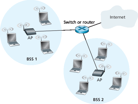
图 7.7 IEEE 802.11 局域网架构
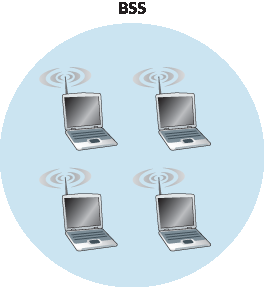
图 7.8 一个 IEEE 802.11 自组网络
如 第 7.1 节 所述,部署了 AP 的无线局域网通常被称为 基础设施无线局域网,其中“基础设施”包括 AP 和将 AP 与路由器连接的有线以太网基础设施。图 7.8 显示 IEEE 802.11 终端也可以组合在一起形成一个自组网络——该网络没有中央控制,也不连接到“外部世界”。此类网络是由彼此接近、有通信需求、并且所在位置没有现有网络基础设施的移动设备“即时”组建的。当人们带着笔记本聚在一起(例如在会议室、火车或汽车中)并希望在没有集中式 AP 的情况下交换数据时,可能会形成自组网络。随着可通信的便携设备日益普及,自组网络受到了广泛关注。不过在本节中,我们将重点关注基础设施无线局域网。
Figure 7.7 illustrates the principal components of the 802.11 wireless LAN architecture. The fundamental building block of the 802.11 architecture is the basic service set (BSS). A BSS contains one or more wireless stations and a central base station, known as an access point (AP) in 802.11 parlance. Figure 7.7 shows the AP in each of two BSSs connecting to an interconnection device (such as a switch or router), which in turn leads to the Internet. In a typical home network, there is one AP and one router (typically integrated together as one unit) that connects the BSS to the Internet.
As with Ethernet devices, each 802.11 wireless station has a 6-byte MAC address that is stored in the firmware of the station’s adapter (that is, 802.11 network interface card). Each AP also has a MAC address for its wireless interface. As with Ethernet, these MAC addresses are administered by IEEE and are (in theory) globally unique.
Figure 7.7 IEEE 802.11 LAN architecture
Figure 7.8 An IEEE 802.11 ad hoc network
As noted in Section 7.1, wireless LANs that deploy APs are often referred to as infrastructure wireless LANs, with the “infrastructure” being the APs along with the wired Ethernet infrastructure that interconnects the APs and a router. Figure 7.8 shows that IEEE 802.11 stations can also group themselves together to form an ad hoc network—a network with no central control and with no connections to the “outside world.” Here, the network is formed “on the fly,” by mobile devices that have found themselves in proximity to each other, that have a need to communicate, and that find no preexisting network infrastructure in their location. An ad hoc network might be formed when people with laptops get together (for example, in a conference room, a train, or a car) and want to exchange data in the absence of a centralized AP. There has been tremendous interest in ad hoc networking, as communicating portable devices continue to proliferate. In this section, though, we’ll focus our attention on infrastructure wireless LANs.
频道与关联#
Channels and Association
在 802.11 中,每个无线终端在能够发送或接收网络层数据之前,必须先与一个 AP 建立关联。尽管所有的 802.11 标准都使用了关联机制,但我们将在 IEEE 802.11b/g 的上下文中具体讨论这一主题。
当网络管理员安装一个 AP 时,会为接入点分配一个一词或二词组成的 服务集标识符(SSID)。(例如,在 iPhone 的设置中选择 Wi-Fi 时,会显示一个列表,其中包含范围内每个 AP 的 SSID。)管理员还必须为 AP 分配一个频道号。为理解频道号,请回想一下 802.11 在 2.4 GHz 到 2.4835 GHz 的频率范围内运行。在这 85 MHz 的频段中,802.11 定义了 11 个部分重叠的频道。只有当两个频道之间间隔至少 4 个频道时,它们才是非重叠的。特别地,频道 1、6 和 11 构成了唯一一组三个非重叠的频道。这意味着管理员可以通过在同一物理位置安装三个 802.11b AP,并为其分配频道 1、6 和 11,再将各 AP 与交换机互连,从而构建一个最大总传输速率为 33 Mbps 的无线局域网。
在了解了 802.11 频道的基本知识后,让我们描述一个有趣(而且并不罕见)的情况——所谓的 WiFi 丛林。 WiFi 丛林 指的是无线终端在某一物理位置可以接收到两个或多个 AP 发出的足够强的信号的情形。例如,在纽约市的许多咖啡馆中,无线终端可以接收到来自多个附近 AP 的信号。其中一个 AP 可能由咖啡馆管理,而其他 AP 可能来自咖啡馆附近的居民住宅。这些 AP 很可能处于不同的 IP 子网中,并被独立地分配了频道。
现在假设你携带手机、平板或笔记本电脑进入了这样的 WiFi 丛林,想要接入无线互联网并点一个蓝莓松饼。假设 WiFi 丛林中有五个 AP。为了获得互联网接入,你的无线设备需要加入其中一个子网,因此需要与其中一个 AP 建立关联。关联意味着无线设备在其自身与 AP 之间创建了一条虚拟线路。具体来说,只有与设备关联的 AP 会向该无线设备发送数据帧(即包含数据的数据报帧),无线设备也只通过该关联的 AP 向互联网发送数据帧。但是,你的无线设备是如何与某个特定的 AP 建立关联的?更基本地说,它又是如何知道丛林中是否存在可用的 AP?
802.11 标准要求 AP 定期发送 信标帧,每个信标帧中包含 AP 的 SSID 和 MAC 地址。你的无线设备知道 AP 会发送信标帧,因此会扫描 11 个频道,寻找可能存在的 AP 所发送的信标帧(有些 AP 可能在同一频道上发送——这就是个丛林!)。在通过信标帧获知可用的 AP 后,你(或你的无线设备)会选择其中一个 AP 来建立关联。
802.11 标准并未规定选择可用 AP 的算法;该算法由无线设备中的 802.11 固件和软件的设计者决定。通常,设备会选择其接收到信号强度最高的信标帧所对应的 AP。虽然信号强度较高是好事(参见 图 7.3),但它并不是决定设备性能的唯一因素。特别是,被选中的 AP 虽然信号强,但可能已被多个设备占用(它们需要共享该 AP 的无线带宽),而另一个空闲 AP 仅因信号稍弱而未被选择。因此,近期已有多种选择 AP 的替代方法被提出 [Vasudevan 2005;Nicholson 2006;Sundaresan 2006]。有关如何测量信号强度的有趣且通俗的讨论,请参阅 [Bardwell 2004]。
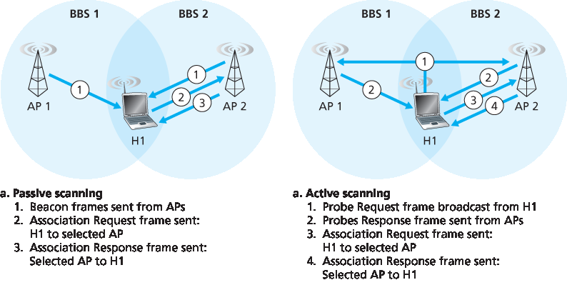
图 7.9 接入点的主动和被动扫描
扫描频道并监听信标帧的过程称为 被动扫描 (参见 图 7.9a)。无线设备也可以进行 主动扫描,通过广播一个探测帧,使无线设备范围内的所有 AP 接收到,如 图 7.9b 所示。AP 会响应探测请求帧,发送一个探测响应帧。无线设备随后可以从这些响应的 AP 中选择一个进行关联。
在选择好要关联的 AP 之后,无线设备会向 AP 发送一个关联请求帧,AP 则回应一个关联响应帧。注意,这一第二次的请求/响应握手在主动扫描中是必要的,因为响应初始探测请求帧的 AP 并不知道设备最终会选择与哪个(可能有多个响应的)AP 建立关联,这与 DHCP 客户端在多个 DHCP 服务器中选择一个服务器的情形非常相似(参见 图 4.21)。一旦与某个 AP 建立了关联,设备通常希望加入该 AP 所属的子网(即 第 4.3.3 节 所描述的 IP 地址意义上的子网)。因此,设备通常会通过 AP 向子网发送一个 DHCP 发现报文(参见 图 4.21),以获取该子网中的 IP 地址。一旦获得地址,其它设备就会将该设备视为具有该子网 IP 地址的另一个主机。
为了与某个特定的 AP 建立关联,可能需要无线设备向 AP 进行身份认证。802.11 无线局域网提供了多种认证与访问机制。一种方法是许多公司采用的方式,即基于设备的 MAC 地址授予对无线网络的访问权限。另一种方法是许多互联网咖啡馆采用的方式,即使用用户名和密码。在这两种情况下,AP 通常会与一个认证服务器通信,使用如 RADIUS [RFC 2865] 或 DIAMETER [RFC 3588] 这样的协议,在无线设备与认证服务器之间传递信息。将认证服务器与 AP 分离,可以让一个认证服务器为多个 AP 提供服务,从而将认证与访问决策集中于单一服务器(这些决策通常是敏感的),并降低 AP 的成本和复杂性。我们将在 第 8 章 中看到,新的 IEEE 802.11i 协议定义了 802.11 协议族的安全机制,正是采用了这种方式。
In 802.11, each wireless station needs to associate with an AP before it can send or receive network- layer data. Although all of the 802.11 standards use association, we’ll discuss this topic specifically in the context of IEEE 802.11b/g.
When a network administrator installs an AP, the administrator assigns a one- or two-word Service Set Identifier (SSID) to the access point. (When you choose Wi-Fi under Setting on your iPhone, for example, a list is displayed showing the SSID of each AP in range.) The administrator must also assign a channel number to the AP. To understand channel numbers, recall that 802.11 operates in the frequency range of 2.4 GHz to 2.4835 GHz. Within this 85 MHz band, 802.11 defines 11 partially overlapping channels. Any two channels are non-overlapping if and only if they are separated by four or more channels. In particular, the set of channels 1, 6, and 11 is the only set of three non-overlapping channels. This means that an administrator could create a wireless LAN with an aggregate maximum transmission rate of 33 Mbps by installing three 802.11b APs at the same physical location, assigning channels 1, 6, and 11 to the APs, and interconnecting each of the APs with a switch.
Now that we have a basic understanding of 802.11 channels, let’s describe an interesting (and not completely uncommon) situation—that of a WiFi jungle. A WiFi jungle is any physical location where a wireless station receives a sufficiently strong signal from two or more APs. For example, in many cafés in New York City, a wireless station can pick up a signal from numerous nearby APs. One of the APs might be managed by the café, while the other APs might be in residential apartments near the café. Each of these APs would likely be located in a different IP subnet and would have been independently assigned a channel.
Now suppose you enter such a WiFi jungle with your phone, tablet, or laptop, seeking wireless Internet access and a blueberry muffin. Suppose there are five APs in the WiFi jungle. To gain Internet access, your wireless device needs to join exactly one of the subnets and hence needs to associate with exactly one of the APs. Associating means the wireless device creates a virtual wire between itself and the AP. Specifically, only the associated AP will send data frames (that is, frames containing data, such as a datagram) to your wireless device, and your wireless device will send data frames into the Internet only through the associated AP. But how does your wireless device associate with a particular AP? And more fundamentally, how does your wireless device know which APs, if any, are out there in the jungle?
The 802.11 standard requires that an AP periodically send beacon frames, each of which includes the AP’s SSID and MAC address. Your wireless device, knowing that APs are sending out beacon frames, scans the 11 channels, seeking beacon frames from any APs that may be out there (some of which may be transmitting on the same channel—it’s a jungle out there!). Having learned about available APs from the beacon frames, you (or your wireless device) select one of the APs for association.
The 802.11 standard does not specify an algorithm for selecting which of the available APs to associate with; that algorithm is left up to the designers of the 802.11 firmware and software in your wireless device. Typically, the device chooses the AP whose beacon frame is received with the highest signal strength. While a high signal strength is good (see, e.g., Figure 7.3), signal strength is not the only AP characteristic that will determine the performance a device receives. In particular, it’s possible that the selected AP may have a strong signal, but may be overloaded with other affiliated devices (that will need to share the wireless bandwidth at that AP), while an unloaded AP is not selected due to a slightly weaker signal. A number of alternative ways of choosing APs have thus recently been proposed [Vasudevan 2005; Nicholson 2006; Sundaresan 2006]. For an interesting and down-to-earth discussion of how signal strength is measured, see [Bardwell 2004].
Figure 7.9 Active and passive scanning for access points
The process of scanning channels and listening for beacon frames is known as passive scanning (see Figure 7.9a). A wireless device can also perform active scanning, by broadcasting a probe frame that will be received by all APs within the wireless device’s range, as shown in Figure 7.9b. APs respond to the probe request frame with a probe response frame. The wireless device can then choose the AP with which to associate from among the responding APs.
After selecting the AP with which to associate, the wireless device sends an association request frame to the AP, and the AP responds with an association response frame. Note that this second request/response handshake is needed with active scanning, since an AP responding to the initial probe request frame doesn’t know which of the (possibly many) responding APs the device will choose to associate with, in much the same way that a DHCP client can choose from among multiple DHCP servers (see Figure 4.21). Once associated with an AP, the device will want to join the subnet (in the IP addressing sense of Section 4.3.3) to which the AP belongs. Thus, the device will typically send a DHCP discovery message (see Figure 4.21) into the subnet via the AP in order to obtain an IP address on the subnet. Once the address is obtained, the rest of the world then views that device simply as another host with an IP address in that subnet.
In order to create an association with a particular AP, the wireless device may be required to authenticate itself to the AP. 802.11 wireless LANs provide a number of alternatives for authentication and access. One approach, used by many companies, is to permit access to a wireless network based on a device’s MAC address. A second approach, used by many Internet cafés, employs usernames and passwords. In both cases, the AP typically communicates with an authentication server, relaying information between the wireless device and the authentication server using a protocol such as RADIUS [RFC 2865] or DIAMETER [RFC 3588]. Separating the authentication server from the AP allows one authentication server to serve many APs, centralizing the (often sensitive) decisions of authentication and access within the single server, and keeping AP costs and complexity low. We’ll see in Chapter 8 that the new IEEE 802.11i protocol defining security aspects of the 802.11 protocol family takes precisely this approach.
7.3.2 802.11 MAC 协议#
7.3.2 The 802.11 MAC Protocol
一旦无线设备与接入点(AP)建立了关联,它就可以开始向 AP 发送和接收数据帧。但由于多个无线设备,或 AP 本身,可能会在同一频道上同时想要传输数据帧,因此需要一种多路访问协议来协调这些传输。在下面的讨论中,我们将把设备或 AP 称为共享多路访问信道的无线“站点”。正如 第 6 章 和 第 7.2.1 节 所讨论的,多路访问协议大致分为三类:信道划分(包括 CDMA)、随机访问和轮流访问。受到以太网及其随机访问协议巨大成功的启发,802.11 的设计者为 802.11 无线局域网选择了一种随机访问协议。这种随机访问协议称为 带碰撞避免的载波监听多路访问(CSMA/CA),简称 CSMA/CA。与以太网中的 CSMA/CD 类似, CSMA/CA 中的“CSMA”代表“载波监听多路访问”,意味着每个站点在发送前会监听信道,如果信道被检测为忙碌,则不会发送。
虽然以太网和 802.11 都使用载波监听随机访问,但这两种 MAC 协议存在重要区别。首先,802.11 不使用碰撞检测,而是使用碰撞避免技术。其次,由于无线信道的误码率较高,802.11(不同于以太网)使用链路层确认/重传(ARQ)机制。我们将在下文介绍 802.11 的碰撞避免与链路层确认机制。
回顾 第 6.3.2 节 和 第 6.4.2 节,以太网的碰撞检测算法中,站点在发送数据时监听信道。如果在发送过程中检测到其他站点也在发送,则会中止发送,并在等待一段随机时间后重试。不同于 802.3 以太网协议,802.11 MAC 协议不实现碰撞检测。原因有两个:
检测碰撞需要站点能够同时发送(自身信号)和接收(判断是否有其他站点也在发送)。由于在 802.11 适配器中,接收信号的强度通常远小于发送信号的强度,因此构建能够检测碰撞的硬件成本高昂。
更重要的是,即使适配器能够同时发送与监听(并在检测到信道忙碌时中止发送),由于隐藏终端问题和信号衰减(见 第 7.2 节),适配器仍然无法检测所有碰撞。
由于 802.11 无线局域网不使用碰撞检测,一旦站点开始发送帧,它将完整地发送该帧;也就是说,一旦开始发送就不可中断。可以预料的是,在碰撞频繁的情况下发送整个帧(尤其是较长的帧)会显著降低多路访问协议的性能。为了减少碰撞发生的可能性,802.11 采用了几种碰撞避免技术,我们将在下文介绍。
在讨论碰撞避免之前,我们先来看 802.11 的 链路层确认 机制。回顾 第 7.2 节,当无线 LAN 中的站点发送帧时,帧可能由于各种原因未能完整到达接收端。为应对这种非忽略不计的失败概率,802.11 MAC 协议使用链路层确认机制。如 图 7.10 所示,当接收站点接收到通过 CRC 校验的帧后,会在一段称为 短帧间隔(SIFS) 的短时间后,发送确认帧。如果发送站点在设定时间内未收到确认帧,则认为发生了错误,并使用 CSMA/CA 协议重新访问信道重发帧。如果在固定次数的重传后仍未收到确认帧,发送站点将放弃并丢弃该帧。
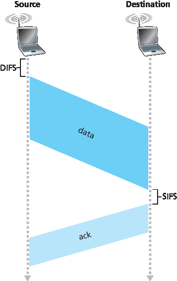
图 7.10 802.11 使用链路层确认
在介绍了 802.11 如何使用链路层确认后,我们现在可以描述 802.11 的 CSMA/CA 协议。假设某个站点(无线设备或 AP)有一个帧要发送。
如果该站点最初检测到信道空闲,它将在一段称为 分布式帧间隔(DIFS) 的短时间后发送其帧;见 图 7.10。
否则,站点将使用二进制指数退避算法(见 第 6.3.2 节)选择一个随机退避值,并在 DIFS 后信道被检测为空闲时开始倒计时。信道处于忙碌状态时,计数器值保持冻结。
当计数器减至 0(注意这只能在信道空闲时发生)时,站点发送整个帧并等待确认。
如果收到确认,发送站点就知道其帧已被正确接收。如果站点还有其他帧要发送,它将从第 2 步重新开始 CSMA/CA 协议。如果未收到确认,发送站点将重新进入第 2 步的退避阶段,并从更大的间隔中选择新的随机值。
回顾以太网的 CSMA/CD 多路访问协议(第 6.3.2 节),站点在检测到信道空闲后立即开始发送。而在 CSMA/CA 中,尽管检测到信道空闲,站点在倒计时期间仍会避免发送。为什么 CSMA/CD 和 CSMA/CA 在这里采取了不同的策略?
为回答这个问题,我们设想一个场景,其中两个站点都有一个数据帧要发送,但由于都检测到第三个站点正在发送,因此两者都未立即发送。在以太网的 CSMA/CD 中,这两个站点会在检测到第三个站点发送结束后立即发送,导致碰撞。但这并不是严重问题,因为两个站点都会中止发送,从而避免剩余帧的无效传输。
然而在 802.11 中情况不同。由于 802.11 不检测碰撞并中止传输,碰撞时帧将被完整发送。因此 802.11 的目标是尽可能避免碰撞。在 802.11 中,如果两个站点检测到信道忙碌,它们会立即进入随机退避阶段,并希望选取不同的退避值。如果退避值确实不同,一旦信道空闲,其中一个站点会比另一个更早开始发送(如果两个站点之间不是隐藏终端),则“失败”的站点会听到“成功”站点的信号,冻结其计数器,并在成功站点完成传输前不再发送。通过这种方式可以避免代价高昂的碰撞。
当然,在此场景下 802.11 仍可能发生碰撞:两个站点可能互为隐藏终端,或者两个站点选取的退避值非常接近,以致先发送站点的信号尚未到达第二个站点。请回忆我们在讨论 图 6.12 中的随机访问算法时遇到的类似问题。
Once a wireless device is associated with an AP, it can start sending and receiving data frames to and from the access point. But because multiple wireless devices, or the AP itself may want to transmit data frames at the same time over the same channel, a multiple access protocol is needed to coordinate the transmissions. In the following, we’ll refer to the devices or the AP as wireless “stations” that share the multiple access channel. As discussed in Chapter 6 and Section 7.2.1, broadly speaking there are three classes of multiple access protocols: channel partitioning (including CDMA), random access, and taking turns. Inspired by the huge success of Ethernet and its random access protocol, the designers of 802.11 chose a random access protocol for 802.11 wireless LANs. This random access protocol is referred to as CSMA with collision avoidance, or more succinctly as CSMA/CA. As with Ethernet’s CSMA/CD, the “CSMA” in CSMA/CA stands for “carrier sense multiple access,” meaning that each station senses the channel before transmitting, and refrains from transmitting when the channel is sensed busy. Although both Ethernet and 802.11 use carrier-sensing random access, the two MAC protocols have important differences. First, instead of using collision detection, 802.11 uses collision- avoidance techniques. Second, because of the relatively high bit error rates of wireless channels, 802.11 (unlike Ethernet) uses a link-layer acknowledgment/retransmission (ARQ) scheme. We’ll describe 802.11’s collision-avoidance and link-layer acknowledgment schemes below.
Recall from Sections 6.3.2 and 6.4.2 that with Ethernet’s collision-detection algorithm, an Ethernet station listens to the channel as it transmits. If, while transmitting, it detects that another station is also transmitting, it aborts its transmission and tries to transmit again after waiting a small, random amount of time. Unlike the 802.3 Ethernet protocol, the 802.11 MAC protocol does not implement collision detection. There are two important reasons for this:
The ability to detect collisions requires the ability to send (the station’s own signal) and receive (to determine whether another station is also transmitting) at the same time. Because the strength of the received signal is typically very small compared to the strength of the transmitted signal at the 802.11 adapter, it is costly to build hardware that can detect a collision.
More importantly, even if the adapter could transmit and listen at the same time (and presumably abort transmission when it senses a busy channel), the adapter would still not be able to detect all collisions, due to the hidden terminal problem and fading, as discussed in Section 7.2.
Because 802.11wireless LANs do not use collision detection, once a station begins to transmit a frame, it transmits the frame in its entirety; that is, once a station gets started, there is no turning back. As one might expect, transmitting entire frames (particularly long frames) when collisions are prevalent can significantly degrade a multiple access protocol’s performance. In order to reduce the likelihood of collisions, 802.11 employs several collision-avoidance techniques, which we’ll shortly discuss.
Before considering collision avoidance, however, we’ll first need to examine 802.11’s link-layer acknowledgment scheme. Recall from Section 7.2 that when a station in a wireless LAN sends a frame, the frame may not reach the destination station intact for a variety of reasons. To deal with this non-negligible chance of failure, the 802.11 MAC protocol uses link-layer acknowledgments. As shown in Figure 7.10, when the destination station receives a frame that passes the CRC, it waits a short period of time known as the Short Inter-frame Spacing (SIFS) and then sends back an acknowledgment frame. If the transmitting station does not receive an acknowledgment within a given amount of time, it assumes that an error has occurred and retransmits the frame, using the CSMA/CA protocol to access the channel. If an acknowledgment is not received after some fixed number of retransmissions, the transmitting station gives up and discards the frame.
Figure 7.10 802.11 uses link-layer acknowledgments
Having discussed how 802.11 uses link-layer acknowledgments, we’re now in a position to describe the 802.11 CSMA/CA protocol. Suppose that a station (wireless device or an AP) has a frame to transmit.
If initially the station senses the channel idle, it transmits its frame after a short period of time known as the Distributed Inter-frame Space (DIFS); see Figure 7.10.
Otherwise, the station chooses a random backoff value using binary exponential backoff (as we encountered in Section 6.3.2) and counts down this value after DIFS when the channel is sensed idle. While the channel is sensed busy, the counter value remains frozen.
When the counter reaches zero (note that this can only occur while the channel is sensed idle), the station transmits the entire frame and then waits for an acknowledgment.
If an acknowledgment is received, the transmitting station knows that its frame has been correctly received at the destination station. If the station has another frame to send, it begins the CSMA/CA protocol at step 2. If the acknowledgment isn’t received, the transmitting station reenters the backoff phase in step 2, with the random value chosen from a larger interval.
Recall that under Ethernet’s CSMA/CD, multiple access protocol (Section 6.3.2), a station begins transmitting as soon as the channel is sensed idle. With CSMA/CA, however, the station refrains from transmitting while counting down, even when it senses the channel to be idle. Why do CSMA/CD and CDMA/CA take such different approaches here?
To answer this question, let’s consider a scenario in which two stations each have a data frame to transmit, but neither station transmits immediately because each senses that a third station is already transmitting. With Ethernet’s CSMA/CD, the two stations would each transmit as soon as they detect that the third station has finished transmitting. This would cause a collision, which isn’t a serious issue in CSMA/CD, since both stations would abort their transmissions and thus avoid the useless transmissions of the remainders of their frames. In 802.11, however, the situation is quite different. Because 802.11 does not detect a collision and abort transmission, a frame suffering a collision will be transmitted in its entirety. The goal in 802.11 is thus to avoid collisions whenever possible. In 802.11, if the two stations sense the channel busy, they both immediately enter random backoff, hopefully choosing different backoff values. If these values are indeed different, once the channel becomes idle, one of the two stations will begin transmitting before the other, and (if the two stations are not hidden from each other) the “losing station” will hear the “winning station’s” signal, freeze its counter, and refrain from transmitting until the winning station has completed its transmission. In this manner, a costly collision is avoided. Of course, collisions can still occur with 802.11 in this scenario: The two stations could be hidden from each other, or the two stations could choose random backoff values that are close enough that the transmission from the station starting first have yet to reach the second station. Recall that we encountered this problem earlier in our discussion of random access algorithms in the context of Figure 6.12.
处理隐藏终端:RTS 与 CTS#
Dealing with Hidden Terminals: RTS and CTS
802.11 的 MAC 协议还包括一个巧妙的(但可选的)预约机制,即使在存在隐藏终端的情况下也能帮助避免碰撞。我们将以 图 7.11 为例探讨这一机制,图中展示了两个无线站点和一个接入点(AP)。这两个无线站点都在 AP 的范围内(其覆盖范围用阴影圆圈表示),并都已与 AP 建立了关联。然而,由于信号衰减,两个无线站点的信号范围被限制在图中所示的阴影圆圈内部。因此,每个无线站点对另一个都是隐藏的,尽管它们都对 AP 可见。
现在让我们来看看隐藏终端为何可能造成问题。假设站点 H1 正在传输一个帧,而在 H1 传输到一半时,站点 H2 想要向 AP 发送一个帧。由于 H2 没有听到来自 H1 的传输,它将在等待一个 DIFS 间隔后开始发送帧,从而导致碰撞。因此,信道将在 H1 传输期间以及 H2 传输期间被浪费。
为避免该问题,IEEE 802.11 协议允许站点使用一个短的 发送请求(RTS) 控制帧和一个短的 允许发送(CTS) 控制帧来预约信道访问权。当发送方想要发送一个 DATA 帧时,它可以首先向 AP 发送一个 RTS 帧,表明发送 DATA 帧和确认(ACK)帧所需的总时间。当 AP 收到 RTS 帧后,会回应一个 CTS 帧。这个 CTS 帧有两个作用:它明确授予发送方发送权限,同时指示其他站点在预约时长内不要发送。
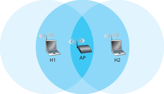
图 7.11 隐藏终端示例:H1 对 H2 不可见,反之亦然
因此,在 图 7.12 中,在发送 DATA 帧之前,H1 首先广播一个 RTS 帧,所有在其范围内的站点(包括 AP)都会收到该帧。然后 AP 响应一个 CTS 帧,所有在其范围内的站点(包括 H1 和 H2)都会收到该帧。站点 H2 在收到 CTS 后,将在 CTS 帧指定的时间内避免发送。RTS、CTS、DATA 和 ACK 帧如 图 7.12 所示。
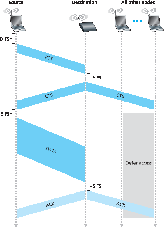
图 7.12 使用 RTS 和 CTS 帧进行碰撞避免
使用 RTS 和 CTS 帧可通过两个重要方式提升性能:
隐藏站点问题被减轻,因为只有在信道已被预约后才发送长 DATA 帧。
由于 RTS 和 CTS 帧较短,涉及 RTS 或 CTS 的碰撞仅持续很短时间。一旦 RTS 和 CTS 成功传输,后续的 DATA 和 ACK 帧应能不发生碰撞地顺利传输。
我们建议你查看本教材网站中的 802.11 小程序。该交互式小程序展示了 CSMA/CA 协议,包括 RTS/CTS 交换序列。
尽管 RTS/CTS 交换可以帮助减少碰撞,它也会引入延迟并消耗信道资源。因此,RTS/CTS 交换仅在需要为长 DATA 帧预约信道时才会使用(如果使用的话)。在实际中,每个无线站点可以设置一个 RTS 阈值,仅在帧长度超过该阈值时才使用 RTS/CTS 序列。对于许多无线站点,默认的 RTS 阈值大于最大帧长度,因此所有发送的 DATA 帧都跳过 RTS/CTS 序列。
The 802.11 MAC protocol also includes a nifty (but optional) reservation scheme that helps avoid collisions even in the presence of hidden terminals. Let’s investigate this scheme in the context of Figure 7.11, which shows two wireless stations and one access point. Both of the wireless stations are within range of the AP (whose coverage is shown as a shaded circle) and both have associated with the AP. However, due to fading, the signal ranges of wireless stations are limited to the interiors of the shaded circles shown in Figure 7.11. Thus, each of the wireless stations is hidden from the other, although neither is hidden from the AP.
Let’s now consider why hidden terminals can be problematic. Suppose Station H1 is transmitting a frame and halfway through H1’s transmission, Station H2 wants to send a frame to the AP. H2, not hearing the transmission from H1, will first wait a DIFS interval and then transmit the frame, resulting in a collision. The channel will therefore be wasted during the entire period of H1’s transmission as well as during H2’s transmission.
In order to avoid this problem, the IEEE 802.11 protocol allows a station to use a short Request to Send (RTS) control frame and a short Clear to Send (CTS) control frame to reserve access to the channel. When a sender wants to send a DATA frame, it can first send an RTS frame to the AP, indicating the total time required to transmit the DATA frame and the acknowledgment (ACK) frame. When the AP receives the RTS frame, it responds by broadcasting a CTS frame. This CTS frame serves two purposes: It gives the sender explicit permission to send and also instructs the other stations not to send for the reserved duration.
Figure 7.11 Hidden terminal example: H1 is hidden from H2, and vice versa
Thus, in Figure 7.12, before transmitting a DATA frame, H1 first broadcasts an RTS frame, which is heard by all stations in its circle, including the AP. The AP then responds with a CTS frame, which is heard by all stations within its range, including H1 and H2. Station H2, having heard the CTS, refrains from transmitting for the time specified in the CTS frame. The RTS, CTS, DATA, and ACK frames are shown in Figure 7.12.
Figure 7.12 Collision avoidance using the RTS and CTS frames
The use of the RTS and CTS frames can improve performance in two important ways:
The hidden station problem is mitigated, since a long DATA frame is transmitted only after the channel has been reserved.
Because the RTS and CTS frames are short, a collision involving an RTS or CTS frame will last only for the duration of the short RTS or CTS frame. Once the RTS and CTS frames are correctly transmitted, the following DATA and ACK frames should be transmitted without collisions.
You are encouraged to check out the 802.11 applet in the textbook’s Web site. This interactive applet illustrates the CSMA/CA protocol, including the RTS/CTS exchange sequence.
Although the RTS/CTS exchange can help reduce collisions, it also introduces delay and consumes channel resources. For this reason, the RTS/CTS exchange is only used (if at all) to reserve the channel for the transmission of a long DATA frame. In practice, each wireless station can set an RTS threshold such that the RTS/CTS sequence is used only when the frame is longer than the threshold. For many wireless stations, the default RTS threshold value is larger than the maximum frame length, so the RTS/CTS sequence is skipped for all DATA frames sent.
使用 802.11 构建点对点链路#
Using 802.11 as a Point-to-Point Link
至此为止,我们的讨论集中在将 802.11 用于多路访问环境。但我们也应该提到,如果两个节点各自配备一个定向天线,它们可以将定向天线对准对方,并在一个本质上为点对点链路上运行 802.11 协议。鉴于市面上 802.11 硬件成本低廉,配合定向天线和增强的传输功率,802.11 可以成为一种廉价的无线点对点连接手段,通信距离可达数十公里。[Raman 2007] 描述了最早的多跳无线网络之一,该网络在印度恒河平原的乡村中运行,采用点对点的 802.11 链路。
Our discussion so far has focused on the use of 802.11 in a multiple access setting. We should mention that if two nodes each have a directional antenna, they can point their directional antennas at each other and run the 802.11 protocol over what is essentially a point-to-point link. Given the low cost of commodity 802.11 hardware, the use of directional antennas and an increased transmission power allow 802.11 to be used as an inexpensive means of providing wireless point-to-point connections over tens of kilometers distance. [Raman 2007] describes one of the first such multi-hop wireless networks, operating in the rural Ganges plains in India using point-to-point 802.11 links.
7.3.3 IEEE 802.11 帧#
7.3.3 The IEEE 802.11 Frame
虽然 802.11 帧在许多方面与以太网帧相似,但它也包含一些专门用于无线链路的字段。802.11 帧如 图 7.13 所示。帧中各字段上方的数字表示字段的字节长度;帧控制字段中各子字段上方的数字表示子字段的比特长度。现在我们来研究帧中的字段,以及帧控制字段中一些较重要的子字段。
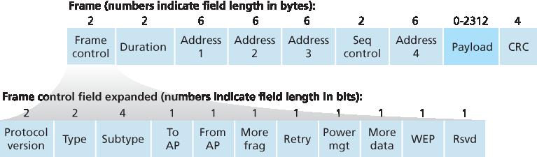
图 7.13 802.11 帧
Although the 802.11 frame shares many similarities with an Ethernet frame, it also contains a number of fields that are specific to its use for wireless links. The 802.11 frame is shown in Figure 7.13. The numbers above each of the fields in the frame represent the lengths of the fields in bytes; the numbers above each of the subfields in the frame control field represent the lengths of the subfields in bits. Let’s now examine the fields in the frame as well as some of the more important subfields in the frame’s control field.
Figure 7.13 The 802.11 frame
有效载荷与 CRC 字段#
Payload and CRC Fields
帧的核心部分是有效载荷,通常由一个 IP 数据报或一个 ARP 包组成。虽然该字段允许的最大长度为 2312 字节,但通常小于 1500 字节,承载一个 IP 数据报或一个 ARP 包。与以太网帧一样,802.11 帧包含一个 32 位的循环冗余校验(CRC),以便接收端检测接收到的帧中的比特错误。正如我们所见,相比于有线 LAN,无线 LAN 中的比特错误更常见,因此 CRC 在此更为有用。
At the heart of the frame is the payload, which typically consists of an IP datagram or an ARP packet. Although the field is permitted to be as long as 2,312 bytes, it is typically fewer than 1,500 bytes, holding an IP datagram or an ARP packet. As with an Ethernet frame, an 802.11 frame includes a 32-bit cyclic redundancy check (CRC) so that the receiver can detect bit errors in the received frame. As we’ve seen, bit errors are much more common in wireless LANs than in wired LANs, so the CRC is even more useful here.
地址字段#
Address Fields
802.11 帧中最显著的差异也许是它有四个地址字段,每个字段可容纳一个 6 字节的 MAC 地址。但为何需要四个地址字段?源 MAC 字段和目标 MAC 字段不就足够了吗,就像以太网中那样?实际上,为了网络互联的目的——特别是将网络层数据报从一个无线站点通过一个接入点(AP)传输到一个路由器接口——需要三个地址字段。第四个地址字段在 AP 之间以自组网模式转发帧时使用。由于我们这里只考虑基础设施网络,我们将重点关注前三个地址字段。802.11 标准对这些字段的定义如下:
地址 2 是发送该帧的站点的 MAC 地址。因此,如果是一个无线站点发送帧,则其 MAC 地址会被插入到地址 2 字段中。类似地,如果是一个 AP 发送帧,则 AP 的 MAC 地址会被插入到地址 2 字段中。
地址 1 是接收该帧的无线站点的 MAC 地址。因此,如果一个移动无线站点发送帧,地址 1 中包含的是目标 AP 的 MAC 地址。类似地,如果一个 AP 发送帧,地址 1 中包含的是目标无线站点的 MAC 地址。
图 7.14 802.11 帧中的地址字段使用:在 H1 与 R1 之间发送帧
要理解地址 3,请回忆一下,BSS(由 AP 和无线站点组成)是某个子网的一部分,该子网通过某个路由器接口与其他子网连接。地址 3 包含这个路由器接口的 MAC 地址。
为了进一步理解地址 3 的用途,让我们结合 图 7.14 来看一个网络互联的例子。在该图中,有两个 AP,每个负责若干无线站点。每个 AP 都直接连接到一个路由器,而该路由器又连接到全球互联网。我们要记住,AP 是一个链路层设备,因此既不“讲”IP,也不理解 IP 地址。现在考虑将一个数据报从路由器接口 R1 发送到无线站点 H1。对路由器来说,它并不知道中间有 AP;在它看来,H1 只是连接到它(路由器)所连接的某个子网中的一个主机。
路由器从数据报的目标地址中知道 H1 的 IP 地址,然后像在普通以太网 LAN 中一样使用 ARP 协议确定 H1 的 MAC 地址。在获取 H1 的 MAC 地址后,路由器接口 R1 将数据报封装进一个以太网帧中。该帧的源地址字段包含 R1 的 MAC 地址,目标地址字段包含 H1 的 MAC 地址。
当以太网帧到达 AP 时,AP 会将 802.3 以太网帧转换为 802.11 帧,再通过无线信道发送。AP 会将地址 1 和地址 2 分别填写为 H1 的 MAC 地址和它自己的 MAC 地址,如上所述。地址 3 则填写 R1 的 MAC 地址。通过这种方式,H1 能从地址 3 中得知将数据报送入子网的路由器接口的 MAC 地址。
现在考虑无线站点 H1 进行回应的情况,即将一个数据报从 H1 发往 R1。
H1 创建一个 802.11 帧,分别将地址 1 和地址 2 填写为 AP 的 MAC 地址和 H1 的 MAC 地址,如上所述。地址 3 填写 R1 的 MAC 地址。
当 AP 接收到 802.11 帧后,会将其转换为以太网帧。该帧的源地址字段为 H1 的 MAC 地址,目标地址字段为 R1 的 MAC 地址。因此,地址 3 能帮助 AP 在构建以太网帧时确定正确的目标 MAC 地址。
总之,地址 3 对于将 BSS 与有线 LAN 互联起到了至关重要的作用。
Perhaps the most striking difference in the 802.11 frame is that it has four address fields, each of which can hold a 6-byte MAC address. But why four address fields? Doesn’t a source MAC field and destination MAC field suffice, as they do for Ethernet? It turns out that three address fields are needed for internetworking purposes—specifically, for moving the network-layer datagram from a wireless station through an AP to a router interface. The fourth address field is used when APs forward frames to each other in ad hoc mode. Since we are only considering infrastructure networks here, let’s focus our attention on the first three address fields. The 802.11 standard defines these fields as follows:
Address 2 is the MAC address of the station that transmits the frame. Thus, if a wireless station transmits the frame, that station’s MAC address is inserted in the address 2 field. Similarly, if an AP transmits the frame, the AP’s MAC address is inserted in the address 2 field.
Address 1 is the MAC address of the wireless station that is to receive the frame. Thus if a mobile wireless station transmits the frame, address 1 contains the MAC address of the destination AP. Similarly, if an AP transmits the frame, address 1 contains the MAC address of the destination wireless station.
Figure 7.14 The use of address fields in 802.11 frames: Sending frames between H1 and R1
To understand address 3, recall that the BSS (consisting of the AP and wireless stations) is part of a subnet, and that this subnet connects to other subnets via some router interface. Address 3 contains the MAC address of this router interface.
To gain further insight into the purpose of address 3, let’s walk through an internetworking example in the context of Figure 7.14. In this figure, there are two APs, each of which is responsible for a number of wireless stations. Each of the APs has a direct connection to a router, which in turn connects to the global Internet. We should keep in mind that an AP is a link-layer device, and thus neither “speaks” IP nor understands IP addresses. Consider now moving a datagram from the router interface R1 to the wireless Station H1. The router is not aware that there is an AP between it and H1; from the router’s perspective, H1 is just a host in one of the subnets to which it (the router) is connected.
The router, which knows the IP address of H1 (from the destination address of the datagram), uses ARP to determine the MAC address of H1, just as in an ordinary Ethernet LAN. After obtaining H1’s MAC address, router interface R1 encapsulates the datagram within an Ethernet frame. The source address field of this frame contains R1’s MAC address, and the destination address field contains H1’s MAC address.
When the Ethernet frame arrives at the AP, the AP converts the 802.3 Ethernet frame to an 802.11 frame before transmitting the frame into the wireless channel. The AP fills in address 1 and address 2 with H1’s MAC address and its own MAC address, respectively, as described above. For address 3, the AP inserts the MAC address of R1. In this manner, H1 can determine (from address 3) the MAC address of the router interface that sent the datagram into the subnet.
Now consider what happens when the wireless station H1 responds by moving a datagram from H1 to R1.
H1 creates an 802.11 frame, filling the fields for address 1 and address 2 with the AP’s MAC address and H1’s MAC address, respectively, as described above. For address 3, H1 inserts R1’s MAC address.
When the AP receives the 802.11 frame, it converts the frame to an Ethernet frame. The source address field for this frame is H1’s MAC address, and the destination address field is R1’s MAC address. Thus, address 3 allows the AP to determine the appropriate destination MAC address when constructing the Ethernet frame.
In summary, address 3 plays a crucial role for internetworking the BSS with a wired LAN.
序列号、持续时间和帧控制字段#
Sequence Number, Duration, and Frame Control Fields
请回忆,在 802.11 协议中,每当一个站点正确接收到另一个站点的帧时,它都会返回一个确认帧。由于确认帧可能丢失,发送站点可能会发送该帧的多个副本。正如我们在 rdt2.1 协议(第 3.4.1 节)讨论中所见,使用序列号可以让接收方区分新传输的帧与之前帧的重传。在 802.11 帧中,序列号字段在链路层中起到与 第 3 章 中传输层相同的作用。
请记住,802.11 协议允许发送站点预留信道一段时间,这段时间包括发送数据帧和发送确认帧的时间。该持续时间值包含在帧的持续时间字段中(无论是数据帧,还是 RTS 与 CTS 帧中)。
如 图 7.13 所示,帧控制字段包含多个子字段。我们这里只简单介绍几个重要子字段;若要了解更完整的内容,建议参考 802.11 标准文档 [Held 2001;Crow 1997;IEEE 802.11 1999]。type 和 subtype 字段用于区分关联、RTS、CTS、ACK 和数据帧。to 和 from 字段用于定义不同地址字段的含义。(这些含义会因使用的是自组网模式还是基础设施模式而变化;在基础设施模式下,还取决于是无线站点还是 AP 在发送帧。)最后,WEP 字段指示是否启用了加密功能(WEP 详见 第 8 章)。
Recall that in 802.11, whenever a station correctly receives a frame from another station, it sends back an acknowledgment. Because acknowledgments can get lost, the sending station may send multiple copies of a given frame. As we saw in our discussion of the rdt2.1 protocol (Section 3.4.1), the use of sequence numbers allows the receiver to distinguish between a newly transmitted frame and the retransmission of a previous frame. The sequence number field in the 802.11 frame thus serves exactly the same purpose here at the link layer as it did in the transport layer in Chapter 3.
Recall that the 802.11 protocol allows a transmitting station to reserve the channel for a period of time that includes the time to transmit its data frame and the time to transmit an acknowledgment. This duration value is included in the frame’s duration field (both for data frames and for the RTS and CTS frames).
As shown in Figure 7.13, the frame control field includes many subfields. We’ll say just a few words about some of the more important subfields; for a more complete discussion, you are encouraged to consult the 802.11 specification [Held 2001; Crow 1997; IEEE 802.11 1999]. The type and subtype fields are used to distinguish the association, RTS, CTS, ACK, and data frames. The to and from fields are used to define the meanings of the different address fields. (These meanings change depending on whether ad hoc or infrastructure modes are used and, in the case of infrastructure mode, whether a wireless station or an AP is sending the frame.) Finally the WEP field indicates whether encryption is being used or not (WEP is discussed in Chapter 8).
7.3.4 同一 IP 子网内的移动性#
7.3.4 Mobility in the Same IP Subnet
为了扩大无线局域网的物理覆盖范围,公司和大学通常会在同一 IP 子网中部署多个 BSS。这自然引发了 BSS 之间移动性的问题——无线站点如何在保持现有 TCP 会话的同时无缝地从一个 BSS 移动到另一个 BSS?正如我们在本小节中将看到的,当多个 BSS 属于同一个子网时,可以以相对简单的方式处理移动性。当站点在不同子网之间移动时,则需要更复杂的移动性管理协议,例如我们将在 第 7.5 节 和 7.6 节 中学习的协议。
现在我们来看一个在同一子网中 BSS 之间移动的具体示例。图 7.15 展示了两个互连的 BSS,一个主机 H1 从 BSS1 移动到 BSS2。由于本例中连接两个 BSS 的互联设备不是路由器,因此两个 BSS 中的所有站点(包括 AP)都属于同一 IP 子网。因此,当 H1 从 BSS1 移动到 BSS2 时,它可以保留其 IP 地址和所有现有的 TCP 连接。如果互联设备是路由器,那么 H1 将必须在其移动到的新子网中获取一个新的 IP 地址。这个地址变化将中断(并最终终止)H1 上所有正在进行的 TCP 连接。在 第 7.6 节 中,我们将看到如何使用诸如移动 IP 这样的网络层移动协议来避免这一问题。
但当 H1 从 BSS1 移动到 BSS2 时,具体会发生什么呢?当 H1 逐渐远离 AP1 时,它检测到来自 AP1 的信号变弱,并开始扫描更强的信号。H1 接收到来自 AP2 的信标帧(在许多公司和大学环境中,AP2 与 AP1 会具有相同的 SSID)。随后,H1 与 AP1 解除关联,并与 AP2 建立关联,同时保留其 IP 地址并保持其现有的 TCP 会话。
这解决了从主机和 AP 的角度来看切换的问题。但 图 7.15 中的交换机呢?它如何知道主机已从一个 AP 移动到另一个 AP?正如你在 第 6 章 中可能记得的那样,交换机是“自学习”的,并会自动构建其转发表。这种自学习特性很好地处理了偶尔的移动(例如,当一名员工从一个部门调到另一个部门);然而,交换机并不是为了支持那些在多个 BSS 之间移动时仍希望保持 TCP 连接的高度移动用户而设计的。为了理解这里的问题,请回忆,在移动之前,交换机的转发表中有一个条目,将 H1 的 MAC 地址与用于到达 H1 的输出接口配对。如果 H1 起初在 BSS1 中,那么发往 H1 的数据报会通过 AP1 被引导到 H1。一旦 H1 与 BSS2 建立关联,它的帧就应该被引导到 AP2。一个解决方案(虽然有些“变通”)是,在建立新关联之后,AP2 向交换机发送一个源地址为 H1 的广播以太网帧。当交换机接收到该帧后,它会更新其转发表,从而使 H1 可通过 AP2 到达。802.11f 标准组织正在开发一种 AP 间协议来处理这些及相关问题。
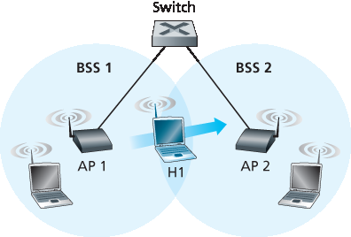
图 7.15 同一子网中的移动性
上述讨论集中在同一个 LAN 子网内的移动性。请回忆我们在 第 6.4.4 节 中学习过的 VLAN,可以将多个 LAN 小岛连接成一个跨越较大地理区域的大型虚拟 LAN。在这种 VLAN 中基站之间的移动性可以以与上述完全相同的方式进行处理 [Yu 2011]。
In order to increase the physical range of a wireless LAN, companies and universities will often deploy multiple BSSs within the same IP subnet. This naturally raises the issue of mobility among the BSSs— how do wireless stations seamlessly move from one BSS to another while maintaining ongoing TCP sessions? As we’ll see in this subsection, mobility can be handled in a relatively straightforward manner when the BSSs are part of the subnet. When stations move between subnets, more sophisticated mobility management protocols will be needed, such as those we’ll study in Sections 7.5 and 7.6.
Let’s now look at a specific example of mobility between BSSs in the same subnet. Figure 7.15 shows two interconnected BSSs with a host, H1, moving from BSS1 to BSS2. Because in this example the interconnection device that connects the two BSSs is not a router, all of the stations in the two BSSs, including the APs, belong to the same IP subnet. Thus, when H1 moves from BSS1 to BSS2, it may keep its IP address and all of its ongoing TCP connections. If the interconnection device were a router, then H1 would have to obtain a new IP address in the subnet in which it was moving. This address change would disrupt (and eventually terminate) any on-going TCP connections at H1. In Section 7.6, we’ll see how a network-layer mobility protocol, such as mobile IP, can be used to avoid this problem.
But what specifically happens when H1 moves from BSS1 to BSS2? As H1 wanders away from AP1, H1 detects a weakening signal from AP1 and starts to scan for a stronger signal. H1 receives beacon frames from AP2 (which in many corporate and university settings will have the same SSID as AP1). H1 then disassociates with AP1 and associates with AP2, while keeping its IP address and maintaining its ongoing TCP sessions.
This addresses the handoff problem from the host and AP viewpoint. But what about the switch in Figure 7.15? How does it know that the host has moved from one AP to another? As you may recall from Chapter 6, switches are “self-learning” and automatically build their forwarding tables. This self- learning feature nicely handles occasional moves (for example, when an employee gets transferred from one department to another); however, switches were not designed to support highly mobile users who want to maintain TCP connections while moving between BSSs. To appreciate the problem here, recall that before the move, the switch has an entry in its forwarding table that pairs H1’s MAC address with the outgoing switch interface through which H1 can be reached. If H1 is initially in BSS1, then a datagram destined to H1 will be directed to H1 via AP1. Once H1 associates with BSS2, however, its frames should be directed to AP2. One solution (a bit of a hack, really) is for AP2 to send a broadcast Ethernet frame with H1’s source address to the switch just after the new association. When the switch receives the frame, it updates its forwarding table, allowing H1 to be reached via AP2. The 802.11f standards group is developing an inter-AP protocol to handle these and related issues.
Figure 7.15 Mobility in the same subnet
Our discussion above has focused on mobility with the same LAN subnet. Recall that VLANs, which we studied in Section 6.4.4, can be used to connect together islands of LANs into a large virtual LAN that can span a large geographical region. Mobility among base stations within such a VLAN can be handled in exactly the same manner as above [Yu 2011].
7.3.5 802.11 的高级特性#
7.3.5 Advanced Features in 802.
我们将以对 802.11 网络中两项高级功能的简短讨论来结束对 802.11 的介绍。正如我们将看到的,这些功能并未在 802.11 标准中完全规定,而是由标准中指定的机制使其成为可能。这允许不同厂商使用各自的(专有)方法来实现这些功能,可能使它们在竞争中占据优势。
We’ll wrap up our coverage of 802.11 with a short discussion of two advanced capabilities found in 802.11 networks. As we’ll see, these capabilities are not completely specified in the 802.11 standard, but rather are made possible by mechanisms specified in the standard. This allows different vendors to implement these capabilities using their own (proprietary) approaches, presumably giving them an edge over the competition.
802.11 速率自适应#
802.11 Rate Adaptation
我们在 图 7.3 中看到,不同的调制技术(以及它们提供的不同传输速率)适用于不同的信噪比(SNR)场景。例如,考虑一个最初距离基站 20 米、信噪比较高的移动 802.11 用户。由于信噪比高,该用户可以使用物理层调制技术与基站通信,这种技术在保持低误码率(BER)的同时提供较高的传输速率。这是一个理想的用户!假设用户开始移动,远离基站,随着距离的增加,信噪比下降。在这种情况下,如果在基站和用户之间使用的 802.11 协议调制技术不变,随着信噪比降低,误码率将变得不可接受地高,最终没有传输的帧能被正确接收。
因此,一些 802.11 实现具备速率自适应能力,能够基于当前或最近的信道特性自适应地选择所使用的物理层调制技术。如果节点连续发送两帧却未收到确认(隐含信道存在比特错误),传输速率将降至下一级速率。如果连续收到 10 帧确认,或跟踪上一次速率回退时间的计时器到期,传输速率将升至上一级速率。该速率自适应机制与 TCP 拥塞控制机制的“探测”理念相同——当条件良好(通过收到 ACK 反映)时,传输速率提升,直到发生“不良”事件(未收到 ACK);当出现“不良”事件时,传输速率下降。因此,802.11 速率自适应与 TCP 拥塞控制类似于一个不断向父母索取更多(如小孩索要糖果,青少年索要更晚的宵禁时间)的孩子,直到父母说“够了!”,孩子退让(但希望条件改善后再次尝试!)。此外,还有许多其他方案被提出以改进该基本自动速率调整机制 [Kamerman 1997;Holland 2001;Lacage 2004]。
We saw earlier in Figure 7.3 that different modulation techniques (with the different transmission rates that they provide) are appropriate for different SNR scenarios. Consider for example a mobile 802.11 user who is initially 20 meters away from the base station, with a high signal-to-noise ratio. Given the high SNR, the user can communicate with the base station using a physical-layer modulation technique that provides high transmission rates while maintaining a low BER. This is one happy user! Suppose now that the user becomes mobile, walking away from the base station, with the SNR falling as the distance from the base station increases. In this case, if the modulation technique used in the 802.11 protocol operating between the base station and the user does not change, the BER will become unacceptably high as the SNR decreases, and eventually no transmitted frames will be received correctly.
For this reason, some 802.11 implementations have a rate adaptation capability that adaptively selects the underlying physical-layer modulation technique to use based on current or recent channel characteristics. If a node sends two frames in a row without receiving an acknowledgment (an implicit indication of bit errors on the channel), the transmission rate falls back to the next lower rate. If 10 frames in a row are acknowledged, or if a timer that tracks the time since the last fallback expires, the transmission rate increases to the next higher rate. This rate adaptation mechanism shares the same “probing” philosophy as TCP’s congestion-control mechanism—when conditions are good (reflected by ACK receipts), the transmission rate is increased until something “bad” happens (the lack of ACK receipts); when something “bad” happens, the transmission rate is reduced. 802.11 rate adaptation and TCP congestion control are thus similar to the young child who is constantly pushing his/her parents for more and more (say candy for a young child, later curfew hours for the teenager) until the parents finally say “Enough!” and the child backs off (only to try again later after conditions have hopefully improved!). A number of other schemes have also been proposed to improve on this basic automatic rate-adjustment scheme [Kamerman 1997; Holland 2001; Lacage 2004].
电源管理#
Power Management
电源是移动设备中宝贵的资源,因此 802.11 标准提供了电源管理能力,允许 802.11 节点最小化其感知、发送和接收功能及其他电路的“开启”时间。802.11 电源管理的工作方式如下。节点能够显式地在睡眠和唤醒状态之间切换(类似于教室里昏昏欲睡的学生!)。节点通过将 802.11 帧头中的电源管理位设置为 1,向接入点表明它将进入睡眠状态。节点中的计时器随后设置为在 AP 计划发送信标帧之前唤醒节点(回想一下,AP 通常每 100 毫秒发送一次信标帧)。由于 AP 从设置的电源传输位得知节点即将进入睡眠,因此它(AP)知道不应向该节点发送任何帧,并会缓冲所有发往该睡眠主机的帧,待稍后发送。
节点将在 AP 发送信标帧之前唤醒,并迅速进入完全激活状态(与昏昏欲睡的学生不同,这种唤醒仅需 250 微秒 [Kamerman 1997]!)。AP 发送的信标帧包含一个列表,列出 AP 缓冲的各节点帧。如果节点没有缓冲帧,则可以回到睡眠状态。否则,节点可以通过向 AP 发送轮询消息显式请求发送缓冲帧。考虑到信标间隔为 100 毫秒,唤醒时间为 250 微秒,以及接收信标帧并检查无缓冲帧所需的同样极短时间,一个无帧发送或接收需求的节点可以 99% 时间处于睡眠状态,从而节省大量能量。
Power is a precious resource in mobile devices, and thus the 802.11 standard provides power- management capabilities that allow 802.11 nodes to minimize the amount of time that their sense, transmit, and receive functions and other circuitry need to be “on.” 802.11 power management operates as follows. A node is able to explicitly alternate between sleep and wake states (not unlike a sleepy student in a classroom!). A node indicates to the access point that it will be going to sleep by setting the power-management bit in the header of an 802.11 frame to 1. A timer in the node is then set to wake up the node just before the AP is scheduled to send its beacon frame (recall that an AP typically sends a beacon frame every 100 msec). Since the AP knows from the set power-transmission bit that the node is going to sleep, it (the AP) knows that it should not send any frames to that node, and will buffer any frames destined for the sleeping host for later transmission.
A node will wake up just before the AP sends a beacon frame, and quickly enter the fully active state (unlike the sleepy student, this wakeup requires only 250 microseconds [Kamerman 1997]!). The beacon frames sent out by the AP contain a list of nodes whose frames have been buffered at the AP. If there are no buffered frames for the node, it can go back to sleep. Otherwise, the node can explicitly request that the buffered frames be sent by sending a polling message to the AP. With an inter-beacon time of 100 msec, a wakeup time of 250 microseconds, and a similarly small time to receive a beacon frame and check to ensure that there are no buffered frames, a node that has no frames to send or receive can be asleep 99% of the time, resulting in a significant energy savings.
7.3.6 个人区域网络:蓝牙和 Zigbee#
7.3.6 Personal Area Networks: Bluetooth and Zigbee
如 图 7.2 所示,IEEE 802.11 WiFi 标准针对的是设备间距离最多达 100 米的通信(802.11 用于带有定向天线的点对点配置时除外)。IEEE 802 系列中的另外两个无线协议是蓝牙和 Zigbee(分别定义在 IEEE 802.15.1 和 IEEE 802.15.4 标准中 [IEEE 802 15 2012])。
As illustrated in Figure 7.2, the IEEE 802.11 WiFi standard is aimed at communication among devices separated by up to 100 meters (except when 802.11 is used in a point-to-point configuration with a directional antenna). Two other wireless protocols in the IEEE 802 family are Bluetooth and Zigbee (defined in the IEEE 802.15.1 and IEEE 802.15.4 standards [IEEE 802 15 2012]).
蓝牙#
Bluetooth
IEEE 802.15.1 网络工作在短距离、低功耗和低成本条件下。本质上,它是一种低功耗、短距离、低速率的“电缆替代”技术,用于连接计算机与其无线键盘、鼠标或其他外设设备;也用于手机、扬声器、耳机及许多其他设备,而 802.11 是一种较高功率、中等距离和较高速率的“接入”技术。因此,802.15.1 网络有时被称为无线个人区域网(WPAN)。802.15.1 的链路层和物理层基于早期的个人区域网络蓝牙规范 [Held 2001,Bisdikian 2001]。802.15.1 网络在 2.4 GHz 免许可无线频段内以时分多址(TDM)方式工作,时隙为 625 微秒。在每个时隙内,发送方在 79 个频道中的一个频道上发送,频道以已知但伪随机的方式从时隙到时隙切换。这种频道跳变方式称为 频跳扩频(FHSS),其作用是在频谱上以时间分布方式扩散传输。802.15.1 可提供最高达 4 Mbps 的数据速率。
802.15.1 网络是自组网:不需要网络基础设施(如接入点)来互连 802.15.1 设备。因此,802.15.1 设备必须自我组织。802.15.1 设备首先被组织成一个最多包含八个活跃设备的 微微网(piconet),如 图 7.16 所示。这些设备中有一个被指定为主设备,其他设备为从设备。主节点实际控制微微网——其时钟决定微微网中的时间,它可以在每个奇数时隙发送数据,而从设备只有在主设备在前一时隙与其通信后才可发送,而且从设备只能向主设备发送数据。除了从设备外,网络中还可以最多有 255 个“停放”设备。这些设备在其状态由主节点从“停放”变为“活跃”之前,不能进行通信。
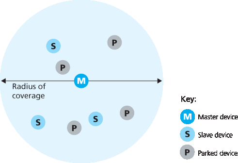
图 7.16 蓝牙微微网
关于 WPAN 的更多信息,有兴趣的读者可参阅蓝牙参考文献 [Held 2001,Bisdikian 2001] 或官方 IEEE 802.15 网站 [IEEE 802.15 2012]。
An IEEE 802.15.1 network operates over a short range, at low power, and at low cost. It is essentially a low-power, short-range, low-rate “cable replacement” technology for interconnecting a computer with its wireless keyboard, mouse or other peripheral device; cellular phones, speakers, headphones, and many other devices, whereas 802.11 is a higher-power, medium-range, higher-rate “access” technology. For this reason, 802.15.1 networks are sometimes referred to as wireless personal area networks (WPANs). The link and physical layers of 802.15.1 are based on the earlier Bluetooth specification for personal area networks [Held 2001, Bisdikian 2001]. 802.15.1 networks operate in the 2.4 GHz unlicensed radio band in a TDM manner, with time slots of 625 microseconds. During each time slot, a sender transmits on one of 79 channels, with the channel changing in a known but pseudo-random manner from slot to slot. This form of channel hopping, known as frequency-hopping spread spectrum (FHSS), spreads transmissions in time over the frequency spectrum. 802.15.1 can provide data rates up to 4 Mbps.
802.15.1 networks are ad hoc networks: No network infrastructure (e.g., an access point) is needed to interconnect 802.15.1 devices. Thus, 802.15.1 devices must organize themselves. 802.15.1 devices are first organized into a piconet of up to eight active devices, as shown in Figure 7.16. One of these devices is designated as the master, with the remaining devices acting as slaves. The master node truly rules the piconet—its clock determines time in the piconet, it can transmit in each odd-numbered slot, and a slave can transmit only after the master has communicated with it in the previous slot and even then the slave can only transmit to the master. In addition to the slave devices, there can also be up to 255 parked devices in the network. These devices cannot communicate until their status has been changed from parked to active by the master node.
Figure 7.16 A Bluetooth piconet
For more information about WPANs, the interested reader should consult the Bluetooth references [Held 2001, Bisdikian 2001] or the official IEEE 802.15 Web site [IEEE 802.15 2012].
Zigbee#
IEEE 另一个标准化的个人区域网是 802.15.4 标准 [IEEE 802.15 2012],即 Zigbee。蓝牙网络提供超过 兆比特每秒的“电缆替代”数据率,而 Zigbee 则针对比蓝牙更低功耗、更低数据率、更低占空比的应用。尽管我们往往认为“越大越快越好”,但并非所有网络应用都需要高带宽及其带来的更高成本(经济成本和功耗)。例如,家庭温度和光线传感器、安全设备以及墙壁开关等都是非常简单、低功耗、低占空比且低成本的设备。因此,Zigbee 非常适合这类设备。Zigbee 定义了 20、40、100 和 250 Kbps 的频道速率,具体取决于频道频率。
Zigbee 网络中的节点分为两类。所谓的“简化功能设备”作为从设备,在单个“全功能设备”的控制下运行,类似于蓝牙的从设备。全功能设备可作为主设备控制多个从设备,并且多个全功能设备可以配置成网状网络,在其中全功能设备之间相互路由帧。Zigbee 共享了许多我们已在其他链路层协议中遇到的协议机制:信标帧和链路层确认(类似 802.11)、带有二进制指数回退的载波监听随机接入协议(类似 802.11 和以太网)、以及固定的、保证的时隙分配(类似 DOCSIS)。
Zigbee 网络可配置为多种不同方式。让我们考虑一个简单的案例,一个全功能设备以使用信标帧的时隙方式控制多个简化功能设备。图 7.17 显示了 Zigbee 网络将时间划分为重复出现的超帧的情况,每个超帧以一个信标帧开始。每个信标帧将超帧分为活动期(设备可发送数据)和非活动期(所有设备包括控制器都可休眠以节约能量)。活动期包含 16 个时隙,其中一些被设备以 CSMA/CA 随机接入方式使用,另一些被控制器分配给特定设备,从而为这些设备提供保证的信道访问。有关 Zigbee 网络的更多细节,请参见 [Baronti 2007,IEEE 802.15.4 2012]。
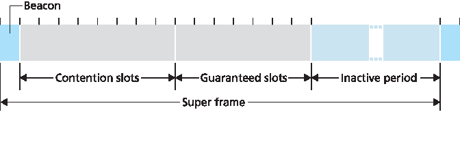
图 7.17 Zigbee 802.15.4 超帧结构
A second personal area network standardized by the IEEE is the 802.15.4 standard [IEEE 802.15 2012] known as Zigbee. While Bluetooth networks provide a “cable replacement” data rate of over a Megabit per second, Zigbee is targeted at lower-powered, lower-data-rate, lower-duty-cycle applications than Bluetooth. While we may tend to think that “bigger and faster is better,” not all network applications need high bandwidth and the consequent higher costs (both economic and power costs). For example, home temperature and light sensors, security devices, and wall-mounted switches are all very simple, low- power, low-duty-cycle, low-cost devices. Zigbee is thus well-suited for these devices. Zigbee defines channel rates of 20, 40, 100, and 250 Kbps, depending on the channel frequency.
Nodes in a Zigbee network come in two flavors. So-called “reduced-function devices” operate as slave devices under the control of a single “full-function device,” much as Bluetooth slave devices. A full- function device can operate as a master device as in Bluetooth by controlling multiple slave devices, and multiple full-function devices can additionally be configured into a mesh network in which full- function devices route frames amongst themselves. Zigbee shares many protocol mechanisms that we’ve already encountered in other link-layer protocols: beacon frames and link-layer acknowledgments (similar to 802.11), carrier-sense random access protocols with binary exponential backoff (similar to 802.11 and Ethernet), and fixed, guaranteed allocation of time slots (similar to DOCSIS).
Zigbee networks can be configured in many different ways. Let’s consider the simple case of a single full-function device controlling multiple reduced-function devices in a time-slotted manner using beacon frames. Figure 7.17 shows the case where the Zigbee network divides time into recurring super frames, each of which begins with a beacon frame. Each beacon frame divides the super frame into an active period (during which devices may transmit) and an inactive period (during which all devices, including the controller, can sleep and thus conserve power). The active period consists of 16 time slots, some of which are used by devices in a CSMA/CA random access manner, and some of which are allocated by the controller to specific devices, thus providing guaranteed channel access for those devices. More details about Zigbee networks can be found at [Baronti 2007, IEEE 802.15.4 2012].
Figure 7.17 Zigbee 802.15.4 super-frame structure