8.9 运行安全:防火墙和入侵检测系统#
8.9 Operational Security: Firewalls and Intrusion Detection Systems
我们在本章中已经看到,互联网并不是一个非常安全的地方——坏人无处不在,制造各种破坏。鉴于互联网的敌对性质,现在让我们考虑一个组织的网络及其网络管理员。从网络管理员的角度来看,世界可以很清楚地分为两类人——好人(属于组织网络,应该能够相对自由地访问组织网络内的资源)和坏人(其他所有人,其访问网络资源的权限必须被严格审查)。在许多组织中,从中世纪的城堡到现代的企业办公楼,都有一个单一的进出点,所有进入和离开组织的好人和坏人都必须经过安全检查。在城堡中,这通常是在吊桥一端的城门处完成;在企业大楼中,则是在安保台进行。在计算机网络中,当进入/离开网络的流量经过安全检查、记录、丢弃或转发时,通常是由称为 防火墙、 入侵检测系统(IDS) 和 入侵防御系统(IPS) 的运行设备完成。
We’ve seen throughout this chapter that the Internet is not a very safe place—bad guys are out there, wreaking all sorts of havoc. Given the hostile nature of the Internet, let’s now consider an organization’s network and the network administrator who administers it. From a network administrator’s point of view, the world divides quite neatly into two camps—the good guys (who belong to the organization’s network, and who should be able to access resources inside the organization’s network in a relatively unconstrained manner) and the bad guys (everyone else, whose access to network resources must be carefully scrutinized). In many organizations, ranging from medieval castles to modern corporate office buildings, there is a single point of entry/exit where both good guys and bad guys entering and leaving the organization are security-checked. In a castle, this was done at a gate at one end of the drawbridge; in a corporate building, this is done at the security desk. In a computer network, when traffic entering/leaving a network is security-checked, logged, dropped, or forwarded, it is done by operational devices known as firewalls, intrusion detection systems (IDSs), and intrusion prevention systems (IPSs).
8.9.1 防火墙#
8.9.1 Firewalls
防火墙是硬件和软件的组合,用于将组织的内部网络与广域互联网隔离开来,允许部分数据包通过,阻止其他数据包通过。防火墙允许网络管理员通过管理进出这些资源的流量,控制外部世界与被管理网络内部资源之间的访问。防火墙有三个目标:
所有进出网络的流量都必须经过防火墙。图 8.33 显示了一个防火墙,位于被管理网络和互联网其余部分之间的边界。虽然大型组织可能使用多层防火墙或分布式防火墙 [Skoudis 2006],但如 图 8.33 所示,将防火墙设置在网络的单一入口点,使得管理和执行安全访问策略更为简单。
只有被本地安全策略授权的流量才被允许通过。所有进出机构网络的流量均通过防火墙,防火墙可以限制访问为授权流量。
防火墙本身不受攻击。防火墙作为连接到网络的设备,如果设计或安装不当,可能被攻破,此时它只提供虚假的安全感(这比没有防火墙更糟!)。
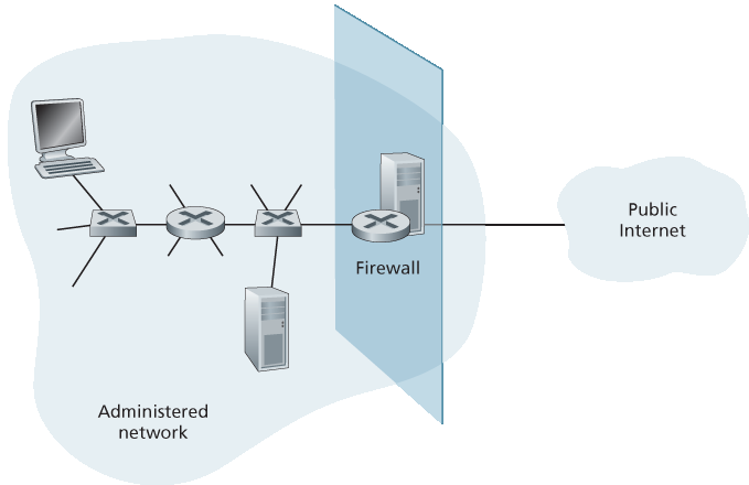
图 8.33 防火墙在被管理网络与外部世界之间的位置
Cisco 和 Check Point 是当今领先的防火墙供应商。你也可以轻松地使用 Linux 服务器上的 iptables(通常随 Linux 一起提供的公共领域软件)创建防火墙(包过滤器)。此外,如 第 4 章 和 第 5 章 所述,防火墙现在经常被实现于路由器中,并通过 SDN 远程控制。
防火墙可分为三类: 传统包过滤器、状态检测过滤器 和 应用网关。我们将在以下小节中依次介绍这些类别。
A firewall is a combination of hardware and software that isolates an organization’s internal network from the Internet at large, allowing some packets to pass and blocking others. A firewall allows a network administrator to control access between the outside world and resources within the administered network by managing the traffic flow to and from these resources. A firewall has three goals:
All traffic from outside to inside, and vice versa, passes through the firewall. Figure 8.33 shows a firewall, sitting squarely at the boundary between the administered network and the rest of the Internet. While large organizations may use multiple levels of firewalls or distributed firewalls
[Skoudis 2006], locating a firewall at a single access point to the network, as shown in Figure 8.33, makes it easier to manage and enforce a security-access policy. - Only authorized traffic, as defined by the local security policy, will be allowed to pass. With all traffic entering and leaving the institutional network passing through the firewall, the firewall can restrict access to authorized traffic. - The firewall itself is immune to penetration. The firewall itself is a device connected to the network. If not designed or installed properly, it can be compromised, in which case it provides only a false sense of security (which is worse than no firewall at all!).
Figure 8.33 Firewall placement between the administered network and the outside world
Cisco and Check Point are two of the leading firewall vendors today. You can also easily create a firewall (packet filter) from a Linux box using iptables (public-domain software that is normally shipped with Linux). Furthermore, as discussed in Chapters 4 and 5, firewalls are now frequently implemented in routers and controlled remotely using SDNs.
Firewalls can be classified in three categories: traditional packet filters, stateful filters, and application gateways. We’ll cover each of these in turn in the following subsections.
传统包过滤器#
Traditional Packet Filters
如 图 8.33 所示,组织通常有一个网关路由器,将其内部网络连接到其 ISP(从而连接到更大的公共互联网)。所有进出内部网络的流量都经过此路由器, 包过滤 就在这台路由器上进行。包过滤器独立地检查每个数据报,根据管理员指定的规则决定该数据报是允许通过还是被丢弃。过滤决策通常基于:
IP 源地址或目标地址
IP 数据报字段中的协议类型:TCP、UDP、ICMP、OSPF 等
TCP 或 UDP 的源端口和目标端口
表 8.5 组织网络 130.207/16 及其 Web 服务器 130.207.244.203 的策略及相应过滤规则
策略
防火墙设置
禁止外部访问 Web。
丢弃所有发往任何 IP 地址的端口 80 的出站数据包。
除组织公共 Web 服务器外,不允许任何 TCP 连接进入。
丢弃所有发往除 130.207.244.203 端口 80 以外 IP 地址的入站 TCP SYN 数据包。
防止网络广播电台占用带宽。
丢弃所有入站 UDP 数据包——DNS 数据包除外。
防止网络被用作 smurf 拒绝服务攻击。
丢弃所有发往“广播”地址(如 130.207.255.255)的 ICMP ping 数据包。
防止网络被 traceroute 探测。
丢弃所有出站的 ICMP TTL 过期流量。
TCP 标志位:SYN、ACK 等
ICMP 消息类型
对进出网络的数据报应用不同规则
对不同路由器接口应用不同规则
网络管理员根据组织的策略配置防火墙。策略可能同时考虑用户生产力、带宽使用以及组织的安全需求。表 8.5 列举了组织可能采用的若干策略及其对应的包过滤器实现方法。例如,如果组织不允许除公共 Web 服务器外的任何入站 TCP 连接,则可以阻止所有入站 TCP SYN 段,除了目标端口为 80 且目标 IP 地址对应 Web 服务器的 TCP SYN 段。如果组织不希望用户用网络广播电台占用带宽,可以阻止所有非关键的 UDP 流量(因为网络广播电台通常使用 UDP)。如果组织不希望其内部网络被外部映射(traceroute),则可以阻止所有出站的 ICMP TTL 过期消息。
过滤策略可以基于地址和端口号的组合。例如,过滤路由器可以允许所有 Telnet 数据报(端口号为 23),但仅允许流向和来自特定 IP 地址列表的 Telnet 数据报。此策略允许与允许列表上的主机之间的 Telnet 连接。不幸的是,基于外部地址的策略无法防止伪造源地址的数据报。
过滤还可以基于 TCP ACK 位是否被设置。这种技巧非常有用,如果组织希望允许内部客户端连接外部服务器,但阻止外部客户端连接内部服务器。
表 8.6 路由器接口的访问控制列表
动作 |
源地址 |
目标地址 |
协议 |
源端口 |
目标端口 |
标志位 |
允许 |
222.22/16 |
222.22/16 之外 |
TCP |
> 1023 |
80 |
任意 |
允许 |
222.22/16 之外 |
222.22/16 |
TCP |
80 |
> 1023 |
ACK |
允许 |
222.22/16 |
222.22/16 之外 |
UDP |
> 1023 |
53 |
— |
允许 |
222.22/16 之外 |
222.22/16 |
UDP |
53 |
> 1023 |
— |
拒绝 |
所有 |
所有 |
所有 |
所有 |
所有 |
所有 |
回想第 3.5 节,每个 TCP 连接的第一个段的 ACK 位为 0,而该连接中所有其他段的 ACK 位均为 1。因此,如果组织想阻止外部客户端发起与内部服务器的连接,只需过滤所有 ACK 位为 0 的入站段。此策略阻断所有来自外部的 TCP 连接,但允许内部发起的连接。
防火墙规则通过路由器上的访问控制列表实现,每个路由器接口拥有自己的列表。表 8.6 显示了针对组织 222.22/16 的一个接口访问控制列表示例。该访问控制列表用于连接路由器与组织外部 ISP 的接口。规则按顺序应用于通过接口的每个数据报。前两条规则允许内部用户访问网页:第一条规则允许所有目标端口为 80 的 TCP 包离开组织网络;第二条规则允许所有源端口为 80 且 ACK 位被设置的 TCP 包进入组织网络。注意,如果外部源尝试与内部主机建立 TCP 连接,即使源或目标端口为 80,该连接也会被阻止。后两条规则允许 DNS 数据包进出组织网络。总之,这个较为严格的访问控制列表阻止了除内部发起的网页流量和 DNS 流量之外的所有流量。[CERT Filtering 2012] 提供了建议的端口/协议包过滤规则列表,用以避免现有网络应用中的若干知名安全漏洞。
As shown in Figure 8.33, an organization typically has a gateway router connecting its internal network to its ISP (and hence to the larger public Internet). All traffic leaving and entering the internal network passes through this router, and it is at this router where packet filtering occurs. A packet filter examines each datagram in isolation, determining whether the datagram should be allowed to pass or should be dropped based on administrator-specific rules. Filtering decisions are typically based on:
IP source or destination address
Protocol type in IP datagram field: TCP, UDP, ICMP, OSPF, and so on
TCP or UDP source and destination port
Table 8.5 Policies and corresponding filtering rules for an organization’s network 130.207/16 with Web server at 130.207.244.203
Policy
Firewall Setting
No outside Web access.
Drop all outgoing packets to any IP address, port 80.
No incoming TCP connections, except those for organization’s public Web server only.
Drop all incoming TCP SYN packets to any IP except 130.207.244.203, port 80.
Prevent Web-radios from eating up the available bandwidth.
Drop all incoming UDP packets—except DNS packets.
Prevent your network from being used for a smurf DoS attack.
Drop all ICMP ping packets going to a “broadcast” address (eg 130.207.255.255).
Prevent your network from being tracerouted.
Drop all outgoing ICMP TTL expired traffic.
TCP flag bits: SYN, ACK, and so on
ICMP message type
Different rules for datagrams leaving and entering the network
Different rules for the different router interfaces
A network administrator configures the firewall based on the policy of the organization. The policy may take user productivity and bandwidth usage into account as well as the security concerns of an organization. Table 8.5 lists a number of possible polices an organization may have, and how they would be addressed with a packet filter. For example, if the organization doesn’t want any incoming TCP connections except those for its public Web server, it can block all incoming TCP SYN segments except TCP SYN segments with destination port 80 and the destination IP address corresponding to the Web server. If the organization doesn’t want its users to monopolize access bandwidth with Internet radio applications, it can block all not-critical UDP traffic (since Internet radio is often sent over UDP). If the organization doesn’t want its internal network to be mapped (tracerouted) by an outsider, it can block all ICMP TTL expired messages leaving the organization’s network.
A filtering policy can be based on a combination of addresses and port numbers. For example, a filtering router could forward all Telnet datagrams (those with a port number of 23) except those going to and coming from a list of specific IP addresses. This policy permits Telnet connections to and from hosts on the allowed list. Unfortunately, basing the policy on external addresses provides no protection against datagrams that have had their source addresses spoofed.
Filtering can also be based on whether or not the TCP ACK bit is set. This trick is quite useful if an organization wants to let its internal clients connect to external servers but wants to prevent external clients from connecting to internal servers.
Table 8.6 An access control list for a router interface
action |
source address |
dest address |
protocol |
source port |
dest port |
flag bit |
allow |
222.22/16 |
outside of 222.22/16 |
TCP |
> 1023 |
80 |
any |
allow |
outside of 222.22/16 |
222.22/16 |
TCP |
80 |
> 1023 |
ACK |
allow |
222.22/16 |
outside of 222.22/16 |
UDP |
> 1023 |
53 |
— |
allow |
outside of 222.22/16 |
222.22/16 |
UDP |
53 |
> 1023 |
— |
deny |
all |
all |
all |
all |
all |
all |
Recall from Section 3.5 that the first segment in every TCP connection has the ACK bit set to 0, whereas all the other segments in the connection have the ACK bit set to 1. Thus, if an organization wants to prevent external clients from initiating connections to internal servers, it simply filters all incoming segments with the ACK bit set to 0. This policy kills all TCP connections originating from the outside, but permits connections originating internally.
Firewall rules are implemented in routers with access control lists, with each router interface having its own list. An example of an access control list for an organization 222.22/16 is shown in Table 8.6. This access control list is for an interface that connects the router to the organization’s external ISPs. Rules are applied to each datagram that passes through the interface from top to bottom. The first two rules together allow internal users to surf the Web: The first rule allows any TCP packet with destination port 80 to leave the organization’s network; the second rule allows any TCP packet with source port 80 and the ACK bit set to enter the organization’s network. Note that if an external source attempts to establish a TCP connection with an internal host, the connection will be blocked, even if the source or destination port is 80. The second two rules together allow DNS packets to enter and leave the organization’s network. In summary, this rather restrictive access control list blocks all traffic except Web traffic initiated from within the organization and DNS traffic. [CERT Filtering 2012] provides a list of recommended port/protocol packet filterings to avoid a number of well-known security holes in existing network applications.
有状态包过滤器#
Stateful Packet Filters
在传统的包过滤器中,过滤决策是对每个数据包独立作出的。有状态过滤器实际上跟踪 TCP 连接,并利用这些信息来做出过滤决策。
表 8.7 有状态过滤器的连接表
源地址 |
目标地址 |
源端口 |
目标端口 |
222.22.1.7 |
37.96.87.123 |
12699 |
80 |
222.22.93.2 |
199.1.205.23 |
37654 |
80 |
222.22.65.143 |
203.77.240.43 |
48712 |
80 |
为了理解有状态过滤器,我们重新审视 表 8.6 中的访问控制列表。虽然该访问控制列表较为严格,但它仍允许任何来自外部且 ACK = 1 且源端口为 80 的数据包通过过滤。这类数据包可能被攻击者利用,试图通过畸形数据包使内部系统崩溃、进行拒绝服务攻击或映射内部网络。天真的解决方案是同时阻止 TCP ACK 数据包,但这种做法会阻止组织内部用户访问网页。
有状态过滤器通过在连接表中跟踪所有正在进行的 TCP 连接来解决此问题。这是可能的,因为防火墙可以通过观察三次握手(SYN、SYNACK 和 ACK)来检测新连接的开始;并且当看到该连接的 FIN 包时,可以检测连接的结束。防火墙还可以(保守地)假设如果在某段时间(例如 60 秒)内未见该连接活动,则该连接已结束。表 8.7 显示了一个防火墙的示例连接表。该连接表表明当前有三个正在进行的 TCP 连接,均由组织内部发起。此外,有状态过滤器在其访问控制列表中增加了“检查连接”这一新列,如 表 8.8 所示。注意,表 8.8 与表 8.6 的访问控制列表相同,只是现在指示两条规则需要检查连接。
让我们通过一些例子来看连接表和扩展访问控制列表如何协同工作。假设攻击者试图通过发送带有 TCP 源端口 80 且 ACK 标志位被设置的数据报向组织网络发送畸形数据包。进一步假设该数据包的源端口号是 12543,源 IP 地址为 150.23.23.155。当该数据包到达防火墙时,防火墙会检查 表 8.7 中的访问控制列表,发现该规则指示需检查连接表后才能允许该数据包进入组织网络。防火墙随即检查连接表,发现该数据包不属于任何正在进行的 TCP 连接,因而拒绝该数据包。作为第二个例子,假设一名内部用户想访问外部网站。由于该用户首先发送 TCP SYN 段,该 TCP 连接被记录在连接表中。当 Web 服务器发送回带有 ACK 位的数据包时,防火墙检查连接表,发现相应连接正在进行,因此允许这些数据包通过,从而不干扰内部用户的网页访问。
表 8.8 有状态过滤器的访问控制列表
动作 |
源地址 |
目标地址 |
协议 |
源端口 |
目标端口 |
标志位 |
检查连接 |
允许 |
222.22/16 |
222.22/16 之外 |
TCP |
> 1023 |
80 |
任意 |
|
允许 |
222.22/16 之外 |
222.22/16 |
TCP |
80 |
> 1023 |
ACK |
X |
允许 |
222.22/16 |
222.22/16 之外 |
UDP |
> 1023 |
53 |
— |
|
允许 |
222.22/16 之外 |
222.22/16 |
UDP |
53 |
> 1023 |
— |
X |
拒绝 |
所有 |
所有 |
所有 |
所有 |
所有 |
所有 |
In a traditional packet filter, filtering decisions are made on each packet in isolation. Stateful filters actually track TCP connections, and use this knowledge to make filtering decisions.
Table 8.7 Connection table for stateful filter
source address |
dest address |
source port |
dest port |
222.22.1.7 |
37.96.87.123 |
12699 |
80 |
222.22.93.2 |
199.1.205.23 |
37654 |
80 |
222.22.65.143 |
203.77.240.43 |
48712 |
80 |
To understand stateful filters, let’s reexamine the access control list in Table 8.6. Although rather restrictive, the access control list in Table 8.6 nevertheless allows any packet arriving from the outside with ACK = 1 and source port 80 to get through the filter. Such packets could be used by attackers in attempts to crash internal systems with malformed packets, carry out denial-of-service attacks, or map the internal network. The naive solution is to block TCP ACK packets as well, but such an approach would prevent the organization’s internal users from surfing the Web.
Stateful filters solve this problem by tracking all ongoing TCP connections in a connection table. This is possible because the firewall can observe the beginning of a new connection by observing a three-way handshake (SYN, SYNACK, and ACK); and it can observe the end of a connection when it sees a FIN packet for the connection. The firewall can also (conservatively) assume that the connection is over when it hasn’t seen any activity over the connection for, say, 60 seconds. An example connection table for a firewall is shown in Table 8.7. This connection table indicates that there are currently three ongoing TCP connections, all of which have been initiated from within the organization. Additionally, the stateful filter includes a new column, “check connection,” in its access control list, as shown in Table 8.8. Note that Table 8.8 is identical to the access control list in Table 8.6, except now it indicates that the connection should be checked for two of the rules.
Let’s walk through some examples to see how the connection table and the extended access control list work hand-in-hand. Suppose an attacker attempts to send a malformed packet into the organization’s network by sending a datagram with TCP source port 80 and with the ACK flag set. Further suppose that this packet has source port number 12543 and source IP address 150.23.23.155. When this packet reaches the firewall, the firewall checks the access control list in Table 8.7, which indicates that the connection table must also be checked before permitting this packet to enter the organization’s network. The firewall duly checks the connection table, sees that this packet is not part of an ongoing TCP connection, and rejects the packet. As a second example, suppose that an internal user wants to surf an external Web site. Because this user first sends a TCP SYN segment, the user’s TCP connection gets recorded in the connection table. When the Web server sends back packets (with the ACK bit necessarily set), the firewall checks the table and sees that a corresponding connection is in progress. The firewall will thus let these packets pass, thereby not interfering with the internal user’s Web surfing activity.
Table 8.8 Access control list for stateful filter
action |
source port |
dest port |
protocol |
source port |
dest port |
flag bit |
check conxion |
allow |
222.22/16 |
outside of 222.22/16 |
TCP |
> 1023 |
80 |
any |
|
allow |
outside of 222.22/16 |
222.22/16 |
TCP |
80 |
> 1023 |
ACK |
X |
allow |
222.22/16 |
outside of 222.22/16 |
UDP |
> 1023 |
53 |
— |
|
allow |
outside of 222.22/16 |
222.22/16 |
UDP |
53 |
> 1023 |
— |
X |
deny |
all |
all |
all |
all |
all |
all |
应用网关#
Application Gateway
在上述示例中,我们看到包级过滤允许组织基于 IP 和 TCP/UDP 头部内容(包括 IP 地址、端口号和确认位)进行粗粒度过滤。但是,如果组织想向受限的内部用户(而非 IP 地址)提供 Telnet 服务呢?如果组织希望这些特权用户在被允许创建外部 Telnet 会话前先进行身份验证呢?这类任务超出了传统和有状态过滤器的能力。实际上,关于内部用户身份的信息属于应用层数据,不包含在 IP/TCP/UDP 头部。
为了实现更细粒度的安全,防火墙必须结合包过滤器与应用网关。应用网关超越 IP/TCP/UDP 头部,根据应用数据做出策略决策。应用网关 是一个特定应用的服务器,所有应用数据(入站和出站)都必须通过它。多个应用网关可以运行在同一主机上,但每个网关是独立的服务器,运行自己的进程。
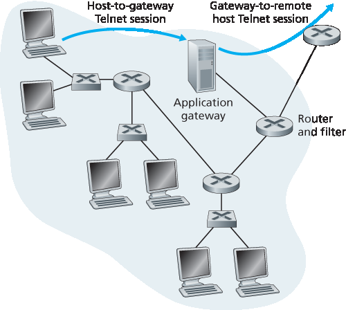
图 8.34 由应用网关和过滤器组成的防火墙
为了理解应用网关,让我们设计一个防火墙,只允许受限的内部用户进行外部 Telnet 连接,且阻止所有外部客户端进行内部 Telnet。这样的策略可以通过结合路由器中的包过滤器和 Telnet 应用网关实现,如 图 8.34 所示。路由器的过滤器配置为阻止所有 Telnet 连接,除非其源自应用网关的 IP 地址。这样的过滤器配置迫使所有出站 Telnet 连接必须通过应用网关。现在考虑一个内部用户想进行外部 Telnet 连接。用户必须先与应用网关建立 Telnet 会话。应用网关中运行的程序监听入站 Telnet 会话,并提示用户输入用户 ID 和密码。当用户提供这些信息时,应用网关检查用户是否有权限进行外部 Telnet。如果没有权限,应用网关终止该连接。如果有权限,应用网关(1)提示用户输入要连接的外部主机名,(2)在应用网关与外部主机之间建立 Telnet 会话,且(3)将用户发来的所有数据转发给外部主机,并将外部主机发来的所有数据转发给用户。因此,Telnet 应用网关不仅执行用户授权,还充当 Telnet 服务器和 Telnet 客户端,在用户和远程 Telnet 服务器之间转发信息。请注意,步骤 2 中,过滤器允许应用网关发起的 Telnet 连接到外部。
案例历史
匿名性与隐私
假设你想访问一个有争议的网站(例如政治活动网站),且你(1)不想向该网站透露你的 IP 地址,(2)不想让本地 ISP(可能是你家或办公 ISP)知道你访问了该网站,(3)不想让本地 ISP 看到你与该网站交换的数据。如果你采用传统方法直接连接该网站且不加密,你在这三点上都无法实现隐私。即使使用 SSL,前两点仍然无法实现:你发送的每个数据报中都包含源 IP 地址;你发送的每个数据包的目标地址也容易被本地 ISP 嗅探。
为了实现隐私和匿名性,你可以结合使用可信代理服务器和 SSL,如 图 8.35 所示。使用此方法,你首先与可信代理建立 SSL 连接。然后通过该 SSL 连接发送对目标网站的 HTTP 请求。代理接收加密的 HTTP 请求后,将其解密并将明文请求转发给网站。网站再响应代理,代理再通过 SSL 将响应转发给你。由于网站只看到代理的 IP 地址,而不是你的客户端地址,因此你确实实现了匿名访问。且因为你与代理间的所有流量都加密,本地 ISP 无法通过记录访问网站或交换数据来侵犯你的隐私。如今许多公司(如 proxify.com)提供这类代理服务。
当然,这种方案的代理知道一切:它知道你的 IP 地址和你访问的网站 IP 地址;它能看到你与网站之间所有明文流量。因此,这种方案的安全性取决于代理的可信度。更强健的方案由 TOR 匿名和隐私服务采用,它将你的流量通过一系列不串通的代理服务器转发 [TOR 2016]。特别地,TOR 允许独立个人为其代理池贡献代理。当用户使用 TOR 连接服务器时,TOR 会随机选择三台代理组成链路,将客户端和服务器间的所有流量通过该链路转发。如此,假设代理不串通,则无人知道你的 IP 地址与目标网站之间发生了通信。此外,尽管最后一台代理与服务器之间传输明文,但该代理并不知道发送和接收明文的 IP 地址。
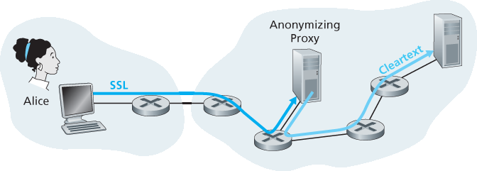
图 8.35 通过代理提供匿名性和隐私
内部网络通常有多个应用网关,例如 Telnet、HTTP、FTP 和电子邮件的网关。事实上,组织的邮件服务器(见 第 2.3 节)和网页缓存就是应用网关。
应用网关也有缺点。首先,每种应用需要一个不同的应用网关。其次,由于所有数据都通过网关转发,会带来性能损失。尤其当多用户或多应用共用同一网关时,这种问题更为突出。最后,客户端软件必须知道如何联系网关,并告诉应用网关要连接的外部服务器。
In the examples above, we have seen that packet-level filtering allows an organization to perform coarse-grain filtering on the basis of the contents of IP and TCP/UDP headers, including IP addresses, port numbers, and acknowledgment bits. But what if an organization wants to provide a Telnet service to a restricted set of internal users (as opposed to IP addresses)? And what if the organization wants such privileged users to authenticate themselves first before being allowed to create Telnet sessions to the outside world? Such tasks are beyond the capabilities of traditional and stateful filters. Indeed, information about the identity of the internal users is application-layer data and is not included in the IP/TCP/UDP headers.
To have finer-level security, firewalls must combine packet filters with application gateways. Application gateways look beyond the IP/TCP/UDP headers and make policy decisions based on application data. An application gateway is an application-specific server through which all application data (inbound and outbound) must pass. Multiple application gateways can run on the same host, but each gateway is a separate server with its own processes.
Figure 8.34 Firewall consisting of an application gateway and a filter
To get some insight into application gateways, let’s design a firewall that allows only a restricted set of internal users to Telnet outside and prevents all external clients from Telneting inside. Such a policy can be accomplished by implementing a combination of a packet filter (in a router) and a Telnet application gateway, as shown in Figure 8.34. The router’s filter is configured to block all Telnet connections except those that originate from the IP address of the application gateway. Such a filter configuration forces all outbound Telnet connections to pass through the application gateway. Consider now an internal user who wants to Telnet to the outside world. The user must first set up a Telnet session with the application gateway. An application running in the gateway, which listens for incoming Telnet sessions, prompts the user for a user ID and password. When the user supplies this information, the application gateway checks to see if the user has permission to Telnet to the outside world. If not, the Telnet connection from the internal user to the gateway is terminated by the gateway. If the user has permission, then the gateway (1) prompts the user for the host name of the external host to which the user wants to connect, (2) sets up a Telnet session between the gateway and the external host, and (3) relays to the external host all data arriving from the user, and relays to the user all data arriving from the external host. Thus, the Telnet application gateway not only performs user authorization but also acts as a Telnet server and a Telnet client, relaying information between the user and the remote Telnet server. Note that the filter will permit step 2 because the gateway initiates the Telnet connection to the outside world.
CASE HISTORY
ANONYMITY AND PRIVACY
Suppose you want to visit a controversial Web site (for example, a political activist site) and you (1) don’t want to reveal your IP address to the Web site, (2) don’t want your local ISP (which may be your home or office ISP) to know that you are visiting the site, and (3) don’t want your local ISP to see the data you are exchanging with the site. If you use the traditional approach of connecting directly to the Web site without any encryption, you fail on all three counts. Even if you use SSL, you fail on the first two counts: Your source IP address is presented to the Web site in every datagram you send; and the destination address of every packet you send can easily be sniffed by your local ISP.
To obtain privacy and anonymity, you can instead use a combination of a trusted proxy server and SSL, as shown in Figure 8.35. With this approach, you first make an SSL connection to the trusted proxy. You then send, into this SSL connection, an HTTP request for a page at the desired site. When the proxy receives the SSL-encrypted HTTP request, it decrypts the request and forwards the cleartext HTTP request to the Web site. The Web site then responds to the proxy, which in turn forwards the response to you over SSL. Because the Web site only sees the IP address of the proxy, and not of your client’s address, you are indeed obtaining anonymous access to the Web site. And because all traffic between you and the proxy is encrypted, your local ISP cannot invade your privacy by logging the site you visited or recording the data you are exchanging. Many companies today (such as proxify .com) make available such proxy services.
Of course, in this solution, your proxy knows everything: It knows your IP address and the IP address of the site you’re surfing; and it can see all the traffic in cleartext exchanged between you and the Web site. Such a solution, therefore, is only as good as the trustworthiness of the proxy. A more robust approach, taken by the TOR anonymizing and privacy service, is to route your traffic through a series of non-colluding proxy servers [TOR 2016]. In particular, TOR allows independent individuals to contribute proxies to its proxy pool. When a user connects to a server using TOR, TOR randomly chooses (from its proxy pool) a chain of three proxies and routes all traffic between client and server over the chain. In this manner, assuming the proxies do not collude, no one knows that communication took place between your IP address and the target Web site. Furthermore, although cleartext is sent between the last proxy and the server, the last proxy doesn’t know what IP address is sending and receiving the cleartext.
Figure 8.35 Providing anonymity and privacy with a proxy
Internal networks often have multiple application gateways, for example, gateways for Telnet, HTTP, FTP, and e-mail. In fact, an organization’s mail server (see Section 2.3) and Web cache are application gateways.
Application gateways do not come without their disadvantages. First, a different application gateway is needed for each application. Second, there is a performance penalty to be paid, since all data will be relayed via the gateway. This becomes a concern particularly when multiple users or applications are using the same gateway machine. Finally, the client software must know how to contact the gateway when the user makes a request, and must know how to tell the application gateway what external server to connect to.
8.9.2 入侵检测系统#
8.9.2 Intrusion Detection Systems
我们刚才看到,包过滤器(传统和有状态)在决定允许哪些数据包通过防火墙时,会检查 IP、TCP、UDP 和 ICMP 头字段。然而,为了检测许多攻击类型,我们需要进行 深度数据包检测,即不仅看头字段,还要查看数据包携带的实际应用数据。正如在 第 8.9.1 节 中看到的,应用网关通常会进行深度数据包检测。但应用网关仅针对特定应用执行此操作。
显然,还有另一种设备的需求——这种设备不仅检查所有通过的数据包的头部(如包过滤器),还执行深度数据包检测(不同于包过滤器)。当该设备检测到可疑数据包或一系列可疑数据包时,它可以阻止这些数据包进入组织网络。或者,因为该活动只是被视为可疑,该设备也可以允许数据包通过,但向网络管理员发送警报,管理员随后可以更仔细地检查流量并采取适当措施。能在检测到潜在恶意流量时发出警报的设备称为 入侵检测系统(IDS)。能够过滤掉可疑流量的设备称为 入侵防御系统(IPS)。本节我们将一起研究 IDS 和 IPS,因为这些系统最有趣的技术点是它们如何检测可疑流量(而非它们是发出警报还是丢弃数据包)。今后我们统称 IDS 和 IPS 为 IDS 系统。
IDS 可用于检测各种攻击,包括网络映射(例如来自 nmap)、端口扫描、TCP 协议栈扫描、带宽洪泛型 DoS 攻击、蠕虫和病毒、操作系统漏洞攻击以及应用漏洞攻击。(参见 第 1.6 节 了解网络攻击综述。)如今,数千家组织部署了 IDS 系统。这些系统中许多是专有的,由 Cisco、Check Point 和其他安全设备供应商销售。但也有许多是公共领域系统,如极为流行的 Snort IDS 系统(我们稍后将讨论)。
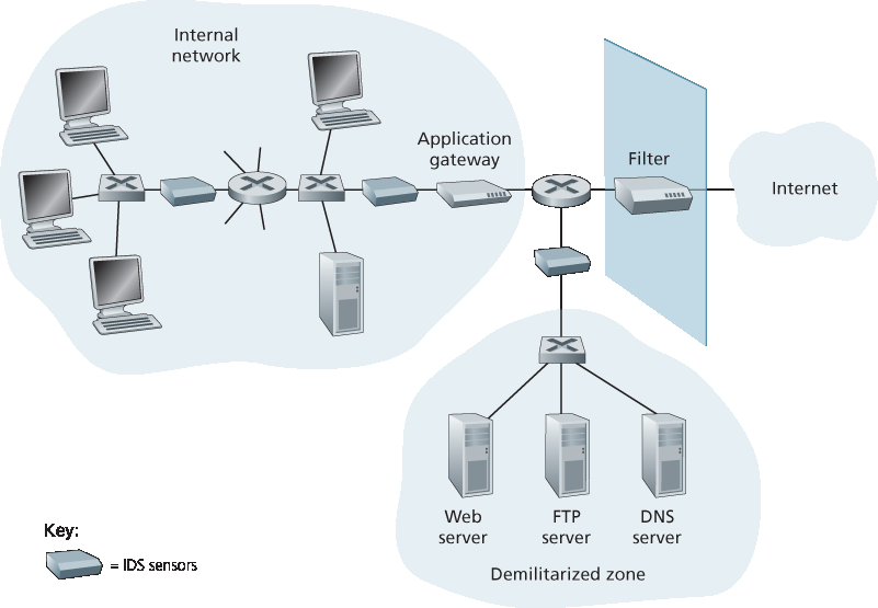
图 8.36 一个部署了过滤器、应用网关和 IDS 传感器的组织
一个组织可能在其网络中部署一个或多个 IDS 传感器。图 8.36 显示了一个有三个 IDS 传感器的组织。当部署多个传感器时,它们通常协同工作,将关于可疑流量活动的信息发送到中央 IDS 处理器,后者收集并整合信息,并在适当时向网络管理员发出警报。在 图 8.36 中,该组织将网络划分为两个区域:一个是由包过滤器和应用网关保护并由 IDS 传感器监控的高安全区域;另一个是只由包过滤器保护但同样由 IDS 传感器监控的较低安全区域——称为 非军事区(DMZ)。请注意,DMZ 包含组织需要与外部通信的服务器,如其公共 Web 服务器和权威 DNS 服务器。
你可能会问,为什么要多个 IDS 传感器?为什么不在 图 8.36 中只在包过滤器后面放一个 IDS 传感器(甚至与包过滤器集成)?我们很快会看到,IDS 不仅需要执行深度数据包检测,还必须将每个经过的数据包与数万个“签名”比较;这可能是相当大的处理量,尤其是当组织从互联网接收数千兆位/秒流量时。通过将 IDS 传感器放置在下游,每个传感器只需看到组织流量的一部分,从而更容易跟上。然而,如今已有高性能 IDS 和 IPS 系统,许多组织实际上只需在其接入路由器附近部署一个传感器即可。
IDS 系统大致分为 基于签名的系统 和 基于异常的系统。基于签名的 IDS 维护一个庞大的攻击签名数据库。每个签名是一组关于入侵活动的规则。签名可能仅是单个数据包的一组特征(例如,源和目标端口号、协议类型以及数据包负载中的特定比特串),也可能涉及一系列数据包。这些签名通常由研究已知攻击的网络安全专家创建。组织的网络管理员可以定制或添加自己的签名到数据库中。
在操作上,基于签名的 IDS 会监听每个经过的数据包,将其与数据库中的签名进行比较。如果某个数据包(或数据包序列)匹配数据库中的签名,IDS 就会发出警报。警报可以通过电子邮件发送给网络管理员,发送到网络管理系统,或仅记录以备将来检查。
虽然基于签名的 IDS 被广泛部署,但存在一些限制。最重要的是,它们需要事先了解攻击以生成准确的签名。换句话说,基于签名的 IDS 对尚未被记录的新攻击完全无感知。另一个缺点是,即使匹配了签名,也不一定是攻击,可能产生误报。最后,因为每个数据包都必须与大量签名进行比对,IDS 可能会因处理过载而无法检测到许多恶意数据包。
基于异常的 IDS 会在观察正常流量时创建流量特征档案。然后它会寻找统计异常的数据流,例如异常高比例的 ICMP 数据包,或端口扫描和 Ping 扫描的突然指数增长。基于异常的 IDS 的优点是它们不依赖于已知攻击的先验知识——即它们可能检测到新的、未被记录的攻击。另一方面,区分正常流量和统计异常流量是一个极具挑战的问题。迄今为止,大多数 IDS 部署主要基于签名,但有些也包含一定的异常检测功能。
We’ve just seen that a packet filter (traditional and stateful) inspects IP, TCP, UDP, and ICMP header fields when deciding which packets to let pass through the firewall. However, to detect many attack types, we need to perform deep packet inspection, that is, look beyond the header fields and into the actual application data that the packets carry. As we saw in Section 8.9.1, application gateways often do deep packet inspection. But an application gateway only does this for a specific application.
Clearly, there is a niche for yet another device—a device that not only examines the headers of all packets passing through it (like a packet filter), but also performs deep packet inspection (unlike a packet filter). When such a device observes a suspicious packet, or a suspicious series of packets, it could prevent those packets from entering the organizational network. Or, because the activity is only
deemed as suspicious, the device could let the packets pass, but send alerts to a network administrator, who can then take a closer look at the traffic and take appropriate actions. A device that generates alerts when it observes potentially malicious traffic is called an intrusion detection system (IDS). A device that filters out suspicious traffic is called an intrusion prevention system (IPS). In this section we study both systems—IDS and IPS—together, since the most interesting technical aspect of these systems is how they detect suspicious traffic (and not whether they send alerts or drop packets). We will henceforth collectively refer to IDS systems and IPS systems as IDS systems.
An IDS can be used to detect a wide range of attacks, including network mapping (emanating, for example, from nmap), port scans, TCP stack scans, DoS bandwidth-flooding attacks, worms and viruses, OS vulnerability attacks, and application vulnerability attacks. (See Section 1.6 for a survey of network attacks.) Today, thousands of organizations employ IDS systems. Many of these deployed systems are proprietary, marketed by Cisco, Check Point, and other security equipment vendors. But many of the deployed IDS systems are public-domain systems, such as the immensely popular Snort IDS system (which we’ll discuss shortly).
Figure 8.36 An organization deploying a filter, an application gateway, and IDS sensors
An organization may deploy one or more IDS sensors in its organizational network. Figure 8.36 shows an organization that has three IDS sensors. When multiple sensors are deployed, they typically work in concert, sending information about suspicious traffic activity to a central IDS processor, which collects and integrates the information and sends alarms to network administrators when deemed appropriate. In Figure 8.36, the organization has partitioned its network into two regions: a high-security region, protected by a packet filter and an application gateway and monitored by IDS sensors; and a lower-security region—referred to as the demilitarized zone (DMZ)—which is protected only by the packet filter, but also monitored by IDS sensors. Note that the DMZ includes the organization’s servers that need to communicate with the outside world, such as its public Web server and its authoritative DNS server.
You may be wondering at this stage, why multiple IDS sensors? Why not just place one IDS sensor just behind the packet filter (or even integrated with the packet filter) in Figure 8.36? We will soon see that an IDS not only needs to do deep packet inspection, but must also compare each passing packet with tens of thousands of “signatures”; this can be a significant amount of processing, particularly if the organization receives gigabits/sec of traffic from the Internet. By placing the IDS sensors further downstream, each sensor sees only a fraction of the organization’s traffic, and can more easily keep up. Nevertheless, high-performance IDS and IPS systems are available today, and many organizations can actually get by with just one sensor located near its access router.
IDS systems are broadly classified as either signature-based systems or anomaly-based systems. A signature-based IDS maintains an extensive database of attack signatures. Each signature is a set of rules pertaining to an intrusion activity. A signature may simply be a list of characteristics about a single packet (e.g., source and destination port numbers, protocol type, and a specific string of bits in the packet payload), or may relate to a series of packets. The signatures are normally created by skilled network security engineers who research known attacks. An organization’s network administrator can customize the signatures or add its own to the database.
Operationally, a signature-based IDS sniffs every packet passing by it, comparing each sniffed packet with the signatures in its database. If a packet (or series of packets) matches a signature in the database, the IDS generates an alert. The alert could be sent to the network administrator in an e-mail message, could be sent to the network management system, or could simply be logged for future inspection.
Signature-based IDS systems, although widely deployed, have a number of limitations. Most importantly, they require previous knowledge of the attack to generate an accurate signature. In other words, a signature-based IDS is completely blind to new attacks that have yet to be recorded. Another disadvantage is that even if a signature is matched, it may not be the result of an attack, so that a false alarm is generated. Finally, because every packet must be compared with an extensive collection of signatures, the IDS can become overwhelmed with processing and actually fail to detect many malicious packets.
An anomaly-based IDS creates a traffic profile as it observes traffic in normal operation. It then looks for packet streams that are statistically unusual, for example, an inordinate percentage of ICMP packets or a sudden exponential growth in port scans and ping sweeps. The great thing about anomaly-based IDS systems is that they don’t rely on previous knowledge about existing attacks—that is, they can potentially detect new, undocumented attacks. On the other hand, it is an extremely challenging problem to distinguish between normal traffic and statistically unusual traffic. To date, most IDS deployments are primarily signature-based, although some include some anomaly-based features.
Snort#
Snort 是一个公共领域、开源的 IDS,已有数十万次部署 [Snort 2012; Koziol 2003]。它可以运行在 Linux、UNIX 和 Windows 平台上。它使用通用嗅探接口 libpcap,该接口也被 Wireshark 和许多其他数据包嗅探器使用。它能轻松处理 100 Mbps 的流量;对于千兆位/秒的安装,可能需要多个 Snort 传感器。
为了了解 Snort,让我们看一个 Snort 签名示例:
alert icmp $EXTERNAL_NET any -> $HOME_NET any
(msg:”ICMP PING NMAP”; dsize: 0; itype: 8;)
该签名匹配任何从外部网络( $EXTERNAL_NET )进入组织网络( $HOME_NET )的 ICMP 数据包,且该包类型为 8(ICMP ping),负载大小为 0(dsize = 0)。由于 nmap(见 第 1.6 节)生成的 ping 数据包具有这些特征,该签名旨在检测 nmap 的 ping 扫描。当数据包匹配该签名时,Snort 会生成包含“ICMP PING NMAP”消息的警报。
Snort 最令人印象深刻的可能是其庞大的用户和安全专家社区维护的签名数据库。通常在新攻击出现几小时内,Snort 社区就会编写并发布攻击签名,然后全球成千上万的 Snort 部署点会下载更新。此外,网络管理员可以利用 Snort 签名语法,根据本组织需求修改已有签名或创建全新签名。
Snort is a public-domain, open source IDS with hundreds of thousands of existing deployments [Snort 2012; Koziol 2003]. It can run on Linux, UNIX, and Windows platforms. It uses the generic sniffing interface libpcap, which is also used by Wireshark and many other packet sniffers. It can easily handle 100 Mbps of traffic; for installations with gibabit/sec traffic rates, multiple Snort sensors may be needed.
To gain some insight into Snort, let’s take a look at an example of a Snort signature:
alert icmp $EXTERNAL_NET any -> $HOME_NET any
(msg:”ICMP PING NMAP”; dsize: 0; itype: 8;)
This signature is matched by any ICMP packet that enters the organization’s network ($HOME_NET) from the outside ($EXTERNAL_NET), is of type 8 (ICMP ping), and has an empty payload (dsize = 0). Since nmap (see Section 1.6) generates ping packets with these specific characteristics, this signature is designed to detect nmap ping sweeps. When a packet matches this signature, Snort generates an alert that includes the message “ICMP PING NMAP”.
Perhaps what is most impressive about Snort is the vast community of users and security experts that maintain its signature database. Typically within a few hours of a new attack, the Snort community writes and releases an attack signature, which is then downloaded by the hundreds of thousands of Snort deployments distributed around the world. Moreover, using the Snort signature syntax, network administrators can tailor the signatures to their own organization’s needs by either modifying existing signatures or creating entirely new ones.