5.5 SDN 控制平面#
5.5 The SDN Control Plane
在本节中,我们将深入探讨 SDN 控制平面 —— 它是控制网络中所有启用 SDN 功能的设备之间的数据包转发的网络范围逻辑,同时也负责这些设备及其服务的配置和管理。本节的学习建立在我们之前关于通用 SDN 转发的讨论之上,参见 第 4.4 节,因此在继续之前你可能需要先复习那一节,以及本章的 第 5.1 节。与 第 4.4 节 一样,我们将再次采用 SDN 领域中常用的术语,将网络中的转发设备称为“分组交换机”(或简称交换机,默认指“分组”),因为转发决策可以基于网络层的源/目的地址、链路层的源/目的地址,以及许多传输层、网络层和链路层包头字段中的其他值来做出。
SDN 架构具有以下四个关键特性 [Kreutz 2015]:
基于流的转发。由 SDN 控制的交换机进行的分组转发可以基于任意数量的传输层、网络层或链路层头字段中的值。我们在 第 4.4 节 中看到,OpenFlow1.0 抽象允许基于十一种不同的头字段值进行转发。这与我们在 第 5.2 节 到 第 5.4 节 中学习的传统基于路由器的转发方式形成了鲜明对比,其中 IP 数据报的转发完全基于其目的 IP 地址。回顾 图 5.2,数据包的转发规则被指定在交换机的流表中;SDN 控制平面的任务是计算、管理并在网络中所有交换机上安装这些流表项。
数据平面与控制平面分离。这种分离在 图 5.2 和 图 5.14 中得到了清晰的展示。数据平面由网络中的交换机构成 —— 这些设备相对简单(但速度快),执行其流表中的“匹配 + 动作”规则。控制平面由服务器和软件组成,负责确定并管理交换机的流表。
网络控制功能:不在数据平面交换机中。由于 SDN 中的“S”代表“软件”,所以 SDN 控制平面是以软件实现的并不令人惊讶。然而,与传统路由器不同,这些软件运行在与网络交换机分离且远程的服务器上。如 图 5.14 所示,控制平面本身包含两个组件 —— 一个 SDN 控制器(或网络操作系统 [Gude 2008])和一组网络控制应用。控制器维护准确的网络状态信息(例如远程链路、交换机和主机的状态);将这些信息提供给控制平面中运行的网络控制应用;并提供这些应用监控、编程和控制底层网络设备的机制。尽管 图 5.14 中的控制器被展示为一个集中式的服务器,在实践中控制器只是逻辑上的集中,通常是在多台服务器上实现的,以提供协调的、可扩展的性能和高可用性。
可编程网络。通过运行在控制平面中的网络控制应用程序实现网络的可编程性。这些应用代表了 SDN 控制平面的“大脑”,利用 SDN 控制器提供的 API 来指定和控制网络设备中的数据平面。例如,一个路由网络控制应用可能会确定源和目的地之间的端到端路径(例如,通过使用 SDN 控制器维护的节点状态和链路状态信息执行 Dijkstra 算法)。另一个网络应用可能执行访问控制,即决定哪些分组应在交换机处被阻止,如我们在 第 4.4.3 节 中的第三个示例所示。还有一个应用可能会以实现服务器负载均衡的方式转发分组(我们在 第 4.4.3 节 中考虑的第二个示例)。
通过以上讨论,我们可以看到,SDN 实现了网络功能的显著“解耦” —— 数据平面交换机、SDN 控制器以及网络控制应用是彼此独立的实体,可能分别由不同的供应商和组织提供。这与 SDN 出现之前的模型形成鲜明对比,后者中的交换机/路由器(连同其嵌入式控制平面软件和协议实现)是一个整体的、垂直集成的单元,并由单一供应商销售。SDN 中的这种网络功能解耦被比作从主机计算机(其硬件、系统软件和应用程序都由同一供应商提供)演进到个人计算机(其硬件、操作系统和应用程序彼此分离)。计算硬件、系统软件和应用的解耦被认为催生了一个由三者领域的创新推动的丰富、开放的生态系统;人们希望 SDN 也能带来类似的创新生态。
基于我们对 图 5.14 中 SDN 架构的理解,自然会引出许多问题。流表究竟是如何以及在哪里计算的?当 SDN 控制的设备发生事件(例如附加链路上下变化)时,这些流表是如何更新的?在多个交换机上的流表项又是如何协调,以实现有序一致的网络级功能(例如,将分组从源端转发到目的端的端到端路径,或协调分布式防火墙)?SDN 控制平面的职责就是提供这些以及其他许多功能。
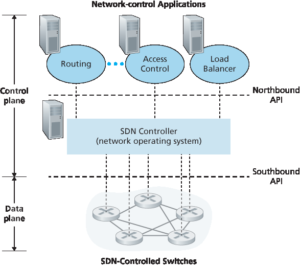
图 5.14 SDN 架构的组成部分:SDN 控制的交换机、SDN 控制器、网络控制应用
In this section, we’ll dive into the SDN control plane—the network-wide logic that controls packet forwarding among a network’s SDN-enabled devices, as well as the configuration and management of these devices and their services. Our study here builds on our earlier discussion of generalized SDN forwarding in Section 4.4, so you might want to first review that section, as well as Section 5.1 of this chapter, before continuing on. As in Section 4.4, we’ll again adopt the terminology used in the SDN literature and refer to the network’s forwarding devices as “packet switches” (or just switches, with “packet” being understood), since forwarding decisions can be made on the basis of network-layer source/destination addresses, link-layer source/destination addresses, as well as many other values in transport-, network-, and link-layer packet-header fields.
Four key characteristics of an SDN architecture can be identified [Kreutz 2015]:
Flow-based forwarding. Packet forwarding by SDN-controlled switches can be based on any number of header field values in the transport-layer, network-layer, or link-layer header. We saw in Section 4.4 that the OpenFlow1.0 abstraction allows forwarding based on eleven different header field values. This contrasts sharply with the traditional approach to router-based forwarding that we studied in Sections 5.2–5.4, where forwarding of IP datagrams was based solely on a datagram’s destination IP address. Recall from Figure 5.2 that packet forwarding rules are specified in a switch’s flow table; it is the job of the SDN control plane to compute, manage and install flow table entries in all of the network’s switches.
Separation of data plane and control plane. This separation is shown clearly in Figures 5.2 and 5.14. The data plane consists of the network’s switches— relatively simple (but fast) devices that
execute the “match plus action” rules in their flow tables. The control plane consists of servers and software that determine and manage the switches’ flow tables. - Network control functions: external to data-plane switches. Given that the “S” in SDN is for “software,” it’s perhaps not surprising that the SDN control plane is implemented in software. Unlike traditional routers, however, this software executes on servers that are both distinct and remote from the network’s switches. As shown in Figure 5.14, the control plane itself consists of two components —an SDN controller (or network operating system [Gude 2008]) and a set of network-control applications. The controller maintains accurate network state information (e.g., the state of remote links, switches, and hosts); provides this information to the network-control applications running in the control plane; and provides the means through which these applications can monitor, program, and control the underlying network devices. Although the controller in Figure 5.14 is shown as a single central server, in practice the controller is only logically centralized; it is typically implemented on several servers that provide coordinated, scalable performance and high availability. - A programmable network. The network is programmable through the network-control applications running in the control plane. These applications represent the “brains” of the SDN control plane, using the APIs provided by the SDN controller to specify and control the data plane in the network devices. For example, a routing network-control application might determine the end-end paths between sources and destinations (e.g., by executing Dijkstra’s algorithm using the node-state and link-state information maintained by the SDN controller). Another network application might perform access control, i.e., determine which packets are to be blocked at a switch, as in our third example in Section 4.4.3. Yet another application might forward packets in a manner that performs server load balancing (the second example we considered in Section 4.4.3).
From this discussion, we can see that SDN represents a significant “unbundling” of network functionality —data plane switches, SDN controllers, and network-control applications are separate entities that may each be provided by different vendors and organizations. This contrasts with the pre-SDN model in which a switch/router (together with its embedded control plane software and protocol implementations) was monolithic, vertically integrated, and sold by a single vendor. This unbundling of network functionality in SDN has been likened to the earlier evolution from mainframe computers (where hardware, system software, and applications were provided by a single vendor) to personal computers (with their separate hardware, operating systems, and applications). The unbundling of computing hardware, system software, and applications has arguably led to a rich, open ecosystem driven by innovation in all three of these areas; one hope for SDN is that it too will lead to a such rich innovation.
Given our understanding of the SDN architecture of Figure 5.14, many questions naturally arise. How and where are the flow tables actually computed? How are these tables updated in response to events at SDN-controlled devices (e.g., an attached link going up/down)? And how are the flow table entries at multiple switches coordinated in such a way as to result in orchestrated and consistent network-wide functionality (e.g., end-to-end paths for forwarding packets from sources to destinations, or coordinated distributed firewalls)? It is the role of the SDN control plane to provide these, and many other, capabilities.
Figure 5.14 Components of the SDN architecture: SDN-controlled switches, the SDN controller, network-control applications
5.5.1 SDN 控制平面:SDN 控制器与 SDN 控制应用#
5.5.1 The SDN Control Plane: SDN Controller and SDN Control Applications
我们先从抽象的角度来讨论 SDN 控制平面,考虑其必须提供的通用能力。正如我们将看到的,这种基于“第一性原理”的抽象方法将引导我们构建出一个整体架构,而该架构也反映了现实中 SDN 控制平面的实现方式。
如上所述,SDN 控制平面大体上分为两个组成部分 —— SDN 控制器和 SDN 网络控制应用。我们先来探讨控制器。自最早的 SDN 控制器 [Gude 2008] 起,已经开发了许多 SDN 控制器;详见 [Kreutz 2015] 所提供的一个非常详尽且最新的综述。图 5.15 展示了一个通用 SDN 控制器的更详细视图。一个控制器的功能可以大致组织为三个层次。我们将采用自底向上的方式来考虑这些层次:
通信层:在 SDN 控制器与受控网络设备之间进行通信。 显然,如果 SDN 控制器要控制远程启用 SDN 的交换机、主机或其他设备的运行,就需要一种协议来在控制器与该设备之间传输信息。此外,设备还必须能够将本地观察到的事件告知控制器(例如,连接链路上下变化的消息、设备刚加入网络的消息,或表示设备处于正常运行状态的心跳信号)。这些事件为 SDN 控制器提供了网络状态的最新视图。该协议构成了控制器架构中的最底层,如 图 5.15 所示。控制器与受控设备之间的通信通过被称为“南向接口”的部分进行。在 第 5.5.2 节 中,我们将学习 OpenFlow —— 一个提供这种通信功能的具体协议。OpenFlow 被实现于大多数(如果不是全部)SDN 控制器中。
网络范围的状态管理层。 SDN 控制平面最终做出的控制决策 —— 例如,为了实现期望的端到端转发而配置所有交换机的流表、实现负载均衡或某种防火墙功能 —— 都要求控制器掌握网络中主机、链路、交换机以及其他 SDN 控制设备的最新状态信息。交换机的流表包含计数器,其值也可能被网络控制应用有效利用;因此,这些值应对应用程序可用。由于控制平面的最终目标是为各种受控设备确定其流表,控制器也可能维护这些流表的副本。这些信息都是 SDN 控制器维护的网络范围“状态”的例子。
网络控制应用层的接口。 控制器通过其“北向接口”与网络控制应用交互。这个 API 允许网络控制应用在状态管理层中读取/写入网络状态和流表。应用可以注册以在状态变化事件发生时接收通知,以便能对来自 SDN 控制设备的网络事件通知作出响应。可能会提供不同类型的 API;我们将看到两个流行的 SDN 控制器使用 REST [Fielding 2000] 请求-响应接口与其应用通信。
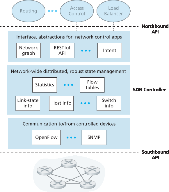
图 5.15 SDN 控制器的组成部分
我们多次指出,SDN 控制器可以被视为“逻辑集中”的,即从外部视角来看(例如从受 SDN 控制的设备和外部网络控制应用的角度),控制器可以被看作是一个单一、整体的服务。然而,这些服务和用于保存状态信息的数据库在实践中是通过一组分布式服务器实现的,目的是实现容错、高可用性或性能优化。由于控制器功能由多个服务器实现,因此必须考虑控制器内部操作的语义(例如维护事件的逻辑时间顺序、一致性、共识等) [Panda 2013]。
这些问题在许多不同的分布式系统中都很常见;详见 [Lamport 1989,Lampson 1996] 所提供的对这些挑战的优雅解决方案。现代控制器如 OpenDaylight [OpenDaylight Lithium 2016] 和 ONOS [ONOS 2016] (参见侧边栏)在架构设计上着重实现逻辑集中但物理分布的控制器平台,为受控设备和网络控制应用提供可扩展的服务与高可用性。
图 5.15 所展示的架构与 2008 年最初提出的 NOX 控制器架构非常相似 [Gude 2008],也与当前的 OpenDaylight [OpenDaylight Lithium 2016] 和 ONOS [ONOS 2016] SDN 控制器类似(参见侧边栏)。我们将在 第 5.5.3 节 中介绍一个控制器操作的示例。但在此之前,让我们先了解控制器通信层所使用的 OpenFlow 协议。
Let’s begin our discussion of the SDN control plane in the abstract, by considering the generic capabilities that the control plane must provide. As we’ll see, this abstract, “first principles” approach will lead us to an overall architecture that reflects how SDN control planes have been implemented in practice.
As noted above, the SDN control plane divides broadly into two components—the SDN controller and the SDN network-control applications. Let’s explore the controller first. Many SDN controllers have been developed since the earliest SDN controller [Gude 2008]; see [Kreutz 2015] for an extremely thorough and up-to-date survey. Figure 5.15 provides a more detailed view of a generic SDN controller. A controller’s functionality can be broadly organized into three layers. Let’s consider these layers in an uncharacteristically bottom-up fashion:
A communication layer: communicating between the SDN controller and controlled network devices. Clearly, if an SDN controller is going to control the operation of a remote SDN-enabled switch, host, or other device, a protocol is needed to transfer information between the controller and that device. In addition, a device must be able to communicate locally-observed events to the controller (e.g., a message indicating that an attached link has gone up or down, that a device has just joined the network, or a heartbeat indicating that a device is up and operational). These events provide the SDN controller with an up-to-date view of the network’s state. This protocol constitutes the lowest layer of the controller architecture, as shown in Figure 5.15. The communication between the controller and the controlled devices cross what has come to be known as the controller’s “southbound” interface. In Section 5.5.2 , we’ll study OpenFlow—a specific protocol that provides this communication functionality. OpenFlow is implemented in most, if not all, SDN controllers.
A network-wide state-management layer. The ultimate control decisions made by the SDN control plane—e.g., configuring flow tables in all switches to achieve the desired end-end forwarding, to implement load balancing, or to implement a particular firewalling capability—will require that the controller have up-to-date information about state of the networks’ hosts, links, switches, and other SDN-controlled devices. A switch’s flow table contains counters whose values might also be profitably used by network-control applications; these values should thus be available to the applications. Since the ultimate aim of the control plane is to determine flow tables for the various controlled devices, a controller might also maintain a copy of these tables. These pieces of information all constitute examples of the network-wide “state” maintained by the SDN controller.
The interface to the network-control application layer. The controller interacts with network- control applications through its “northbound” interface. This API allows network-control applications to read/write network state and flow tables within the state- management layer. Applications can register to be notified when state-change events occur, so that they can take actions in response to network event notifications sent from SDN-controlled devices. Different types of APIs may be provided; we’ll see that two popular SDN controllers communicate
with their applications using a REST [Fielding 2000] request-response interface.
Figure 5.15 Components of an SDN controller
We have noted several times that an SDN controller can be considered to be “logically centralized,” i.e., that the controller may be viewed externally (e.g., from the point of view of SDN-controlled devices and external network-control applications) as a single, monolithic service. However, these services and the databases used to hold state information are implemented in practice by a distributed set of servers for fault tolerance, high availability, or for performance reasons. With controller functions being implemented by a set of servers, the semantics of the controller’s internal operations (e.g., maintaining logical time ordering of events, consistency, consensus, and more) must be considered [Panda 2013].
Such concerns are common across many different distributed systems; see [Lamport 1989, Lampson 1996] for elegant solutions to these challenges. Modern controllers such as OpenDaylight [OpenDaylight Lithium 2016] and ONOS [ONOS 2016] (see sidebar) have placed considerable emphasis on architecting a logically centralized but physically distributed controller platform that provides scalable services and high availability to the controlled devices and network-control applications alike.
The architecture depicted in Figure 5.15 closely resembles the architecture of the originally proposed NOX controller in 2008 [Gude 2008], as well as that of today’s OpenDaylight [OpenDaylight Lithium 2016] and ONOS [ONOS 2016] SDN controllers (see sidebar). We’ll cover an example of controller operation in Section 5.5.3 . First, however, let’s examine the OpenFlow protocol, which lies in the controller’s communication layer.
5.5.2 OpenFlow 协议#
5.5.2 OpenFlow Protocol
OpenFlow 协议 [OpenFlow 2009, ONF 2016] 在 SDN 控制器与 SDN 控制的交换机或其他实现了我们在 第 4.4 节 中学习过的 OpenFlow API 的设备之间运行。OpenFlow 协议基于 TCP 运行,默认端口号为 6653。
从控制器发送到受控交换机的重要消息包括:
Configuration(配置)。该消息允许控制器查询并设置交换机的配置参数。
Modify-State(修改状态)。控制器使用该消息添加、删除或修改交换机流表中的条目,并设置交换机端口属性。
Read-State(读取状态)。控制器使用该消息从交换机的流表和端口收集统计信息和计数器值。
Send-Packet(发送分组)。控制器使用该消息从受控交换机的指定端口发送特定的分组。该消息的有效负载中包含要发送的分组内容。
从 SDN 控制的交换机发送到控制器的消息包括:
Flow-Removed(流移除)。该消息通知控制器某条流表项已被移除,例如由于超时或接收到 modify-state 消息导致。
Port-status(端口状态)。该消息用于交换机通知控制器端口状态的变化。
Packet-in(分组进入)。回顾 第 4.4 节,当分组到达交换机端口且不匹配任何流表项时,会被发送给控制器以进行进一步处理。匹配成功的分组也可以作为匹配结果之一被发送给控制器。packet-in 消息用于将此类分组发送给控制器。
在 [OpenFlow 2009, ONF 2016] 中还定义了其他 OpenFlow 消息。
实践中的原理
Google 的软件定义全球网络
回顾 第 2.6 节 中的案例研究,Google 部署了一个专用的广域网(WAN),用于连接其数据中心和位于 IXP 和 ISP 中的服务器集群。该网络称为 B4,采用了 Google 自行设计的基于 OpenFlow 的 SDN 控制平面。Google 的网络能够在长期运行中将 WAN 链路的利用率提高到接近 70%(是典型链路利用率的两到三倍),并能根据应用的优先级和现有流需求将应用流拆分到多个路径中 [Jain 2013]。
Google 的 B4 网络特别适合 SDN:(i)Google 控制着从 IXP 和 ISP 的边缘服务器到其网络核心中的路由器的所有设备;(ii)最占带宽的应用是在站点之间进行的大规模数据拷贝,在资源拥塞时可以让位于优先级更高的交互式应用;(iii)由于连接的数据中心仅有数十个,集中控制是可行的。
Google 的 B4 网络使用定制构建的交换机,每个交换机实现了稍作扩展的 OpenFlow 版本,并配有一个本地的 Open Flow Agent(OFA),其思想与我们在 图 5.2 中看到的控制代理类似。每个 OFA 又通过一条独立的“带外”网络连接到网络控制服务器(NCS)中的 Open Flow Controller(OFC),这条网络不同于在数据中心之间承载数据中心流量的网络。OFC 提供了 NCS 用于与其控制交换机通信的服务,其本质类似于 图 5.15 中 SDN 架构最底层的服务。在 B4 中,OFC 还执行状态管理功能,在网络信息库(NIB)中保存节点和链路状态。Google 的 OFC 实现基于 ONIX SDN 控制器 [Koponen 2010]。实现了两种路由协议:BGP(用于数据中心之间的路由)和 IS-IS(一种与 OSPF 密切相关的协议,用于数据中心内部路由)。使用 Paxos [Chandra 2007] 来运行 NCS 组件的热备副本以防止故障。
一个流量工程网络控制应用逻辑上位于网络控制服务器之上,与这些服务器交互,为一组应用流提供全局、网络范围的带宽分配。通过 B4,SDN 向全球网络运营商的实际网络迈出了重要的一步。关于 B4 的详细描述参见 [Jain 2013]。
The OpenFlow protocol [OpenFlow 2009, ONF 2016] operates between an SDN controller and an SDN-controlled switch or other device implementing the OpenFlow API that we studied earlier in Section 4.4. The OpenFlow protocol operates over TCP, with a default port number of 6653.
Among the important messages flowing from the controller to the controlled switch are the following:
Configuration. This message allows the controller to query and set a switch’s configuration parameters.
Modify-State. This message is used by a controller to add/delete or modify entries in the switch’s flow table, and to set switch port properties.
Read-State. This message is used by a controller to collect statistics and counter values from the switch’s flow table and ports.
Send-Packet. This message is used by the controller to send a specific packet out of a specified port at the controlled switch. The message itself contains the packet to be sent in its payload.
Among the messages flowing from the SDN-controlled switch to the controller are the following:
Flow-Removed. This message informs the controller that a flow table entry has been removed, for example by a timeout or as the result of a received modify-state message.
Port-status. This message is used by a switch to inform the controller of a change in port status.
Packet-in. Recall from Section 4.4 that a packet arriving at a switch port and not matching any flow table entry is sent to the controller for additional processing. Matched packets may also be sent to the controller, as an action to be taken on a match. The packet-in message is used to send such packets to the controller.
Additional OpenFlow messages are defined in [OpenFlow 2009, ONF 2016].
Principles in Practice
Google’s Software-Defined Global Network
Recall from the case study in Section 2.6 that Google deploys a dedicated wide-area network (WAN) that interconnects its data centers and server clusters (in IXPs and ISPs). This network, called B4, has a Google-designed SDN control plane built on OpenFlow. Google’s network is able to drive WAN links at near 70% utilization over the long run (a two to three fold increase over typical link utilizations) and split application flows among multiple paths based on application priority and existing flow demands [Jain 2013].
The Google B4 network is particularly it well-suited for SDN: (i) Google controls all devices from the edge servers in IXPs and ISPs to routers in their network core; (ii) the most bandwidth- intensive applications are large-scale data copies between sites that can defer to higher-priority interactive applications during times of resource congestion; (iii) with only a few dozen data centers being connected, centralized control is feasible.
Google’s B4 network uses custom-built switches, each implementing a slightly extended version of OpenFlow, with a local Open Flow Agent (OFA) that is similar in spirit to the control agent we encountered in Figure 5.2. Each OFA in turn connects to an Open Flow Controller (OFC) in the network control server (NCS), using a separate “out of band” network, distinct from the network that carries data-center traffic between data centers. The OFC thus provides the services used by the NCS to communicate with its controlled switches, similar in spirit to the lowest layer in the SDN architecture shown in Figure 5.15. In B4, the OFC also performs state management functions, keeping node and link status in a Network Information Base (NIB). Google’s implementation of the OFC is based on the ONIX SDN controller [Koponen 2010]. Two routing protocols, BGP (for routing between the data centers) and IS-IS (a close relative of OSPF, for routing within a data center), are implemented. Paxos [Chandra 2007] is used to execute hot replicas of NCS components to protect against failure.
A traffic engineering network-control application, sitting logically above the set of network control servers, interacts with these servers to provide global, network-wide bandwidth provisioning for groups of application flows. With B4, SDN made an important leap forward into the operational networks of a global network provider. See [Jain 2013] for a detailed description of B4.
5.5.3 数据平面与控制平面交互:一个示例#
5.5.3 Data and Control Plane Interaction: An Example
为了加深我们对 SDN 控制交换机与 SDN 控制器之间交互的理解,让我们考虑 图 5.16 所示的示例,其中使用 Dijkstra 算法(我们在 第 5.2 节 中学习过)来确定最短路径路由。图 5.16 中的 SDN 场景与之前 第 5.2.1 节 和 第 5.3 节 中每台路由器各自控制的场景相比有两个重要区别:
Dijkstra 算法作为一个独立的应用程序在数据交换机之外运行。
数据交换机将链路更新发送给 SDN 控制器,而不是发送给其他交换机。
在这个示例中,假设交换机 s1 与 s2 之间的链路断开;假设实现了最短路径路由,因此 s1、s3 和 s4 的入站和出站流转发规则将受到影响,但 s2 的操作保持不变。我们还假设 OpenFlow 被用作通信层协议,并且控制平面除链路状态路由外不执行其他功能。
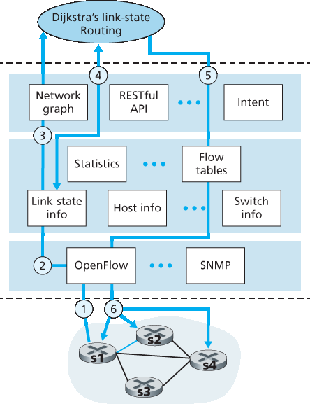
图 5.16 SDN 控制器场景:链路状态变化
交换机 s1 检测到它与 s2 之间的链路故障后,使用 OpenFlow 的 port-status 消息通知 SDN 控制器该链路状态发生变化。
SDN 控制器接收到表明链路状态变化的 OpenFlow 消息,并通知链路状态管理器,后者更新链路状态数据库。
实现 Dijkstra 链路状态路由的网络控制应用此前已注册在链路状态变化时接收通知。该应用随后接收到链路状态变化的通知。
链路状态路由应用与链路状态管理器交互以获取更新后的链路状态;它也可能会查询状态管理层中的其他组件。随后,它计算出新的最小代价路径。
链路状态路由应用接着与流表管理器交互,确定哪些交换机的流表需要更新。
流表管理器随后使用 OpenFlow 协议更新受影响交换机的流表项 —— s1(现在将把发往 s2 的数据包经由 s4 进行转发)、s2(现在将开始从 s1 经由中间交换机 s4 接收数据包)、以及 s4(现在必须转发来自 s1 并目的为 s2 的数据包)。
这个示例虽然简单,但展示了 SDN 控制平面如何提供控制平面服务(在本例中是网络层路由),而这些服务原先是由每个网络路由器各自实现控制来完成的。现在我们可以清楚地认识到,SDN 启用的 ISP 如何能轻松地从最小代价路径路由切换到更为定制化的路由方式。实际上,由于控制器可以随意配置流表,它可以实现任何形式的转发 —— 只需更改其应用控制软件即可。这种更改的便利性与传统每路由器控制平面形成鲜明对比,在后者中,所有路由器中的软件(可能由多个独立供应商提供)都必须进行更改。
In order to solidify our understanding of the interaction between SDN-controlled switches and the SDN controller, let’s consider the example shown in Figure 5.16, in which Dijkstra’s algorithm (which we studied in Section 5.2) is used to determine shortest path routes. The SDN scenario in Figure 5.16 has two important differences from the earlier per-router-control scenario of Sections 5.2.1 and 5.3, where Dijkstra’s algorithm was implemented in each and every router and link-state updates were flooded among all network routers:
Dijkstra’s algorithm is executed as a separate application, outside of the packet switches.
Packet switches send link updates to the SDN controller and not to each other.
In this example, let’s assume that the link between switch s1 and s2 goes down; that shortest path routing is implemented, and consequently and that incoming and outgoing flow forwarding rules at s1, s3, and s4 are affected, but that s2’s operation is unchanged. Let’s also assume that OpenFlow is used as the communication layer protocol, and that the control plane performs no other function other than link-state routing.
Figure 5.16 SDN controller scenario: Link-state change
Switch s1, experiencing a link failure between itself and s2, notifies the SDN controller of the link-state change using the OpenFlow port-status message.
The SDN controller receives the OpenFlow message indicating the link-state change, and notifies the link-state manager, which updates a link-state database.
The network-control application that implements Dijkstra’s link-state routing has previously registered to be notified when link state changes. That application receives the notification of the link-state change.
The link-state routing application interacts with the link-state manager to get updated link state; it might also consult other components in the state-management layer. It then computes the new least-cost paths.
The link-state routing application then interacts with the flow table manager, which determines the flow tables to be updated.
The flow table manager then uses the OpenFlow protocol to update flow table entries at affected switches—s1 (which will now route packets destined to s2 via s4), s2 (which will now begin receiving packets from s1 via intermediate switch s4), and s4 (which must now forward packets from s1 destined to s2).
This example is simple but illustrates how the SDN control plane provides control-plane services (in this case network-layer routing) that had been previously implemented with per-router control exercised in each and every network router. One can now easily appreciate how an SDN-enabled ISP could easily switch from least-cost path routing to a more hand-tailored approach to routing. Indeed, since the controller can tailor the flow tables as it pleases, it can implement any form of forwarding that it pleases —simply by changing its application-control software. This ease of change should be contrasted to the case of a traditional per-router control plane, where software in all routers (which might be provided to the ISP by multiple independent vendors) must be changed.
5.5.4 SDN:过去与未来#
5.5.4 SDN: Past and Future
尽管对 SDN 的强烈兴趣是近年来的现象,但 SDN 的技术根源,尤其是数据平面与控制平面的分离,历史要早得多。2004 年,[Feamster 2004, Lakshman 2004, RFC 3746] 均主张网络的数据平面和控制平面应分离。[van der Merwe 1998] 描述了一个多控制器的 ATM 网络控制框架 [Black 1995],每个控制器管理若干 ATM 交换机。Ethane 项目 [Casado 2007] 首创了基于流的简单以太网交换机网络概念,采用匹配加动作的流表、集中式控制器来管理流的准入和路由,以及未匹配数据包由交换机转发至控制器的机制。2007 年,已有超过 300 台 Ethane 交换机投入运行。Ethane 很快演变为 OpenFlow 项目,其后发生的事情众所周知!
大量研究致力于开发未来的 SDN 架构和功能。正如我们所见,SDN 革命正导致专用单片交换机和路由器(集成数据平面和控制平面)被简单的商用交换硬件和复杂的软件控制平面颠覆性地替代。SDN 的一个推广版本,称为网络功能虚拟化(NFV),同样旨在用简单的商用服务器、交换和存储设备颠覆复杂的中间盒(例如具有专用硬件和专有媒体缓存/服务软件的中间盒):ref:[Gember-Jacobson 2014] <Gember-Jacobson 2014>。另一重要研究方向是将 SDN 概念从自治系统内部扩展到自治系统间 [Gupta 2014]。
实践中的原则
- SDN 控制器案例研究:OpenDaylight 与 ONOS 控制器
在 SDN 的早期,只有单一的 SDN 协议(OpenFlow [McKeown 2008; OpenFlow 2009])和单一的 SDN 控制器(NOX Gude 2008)。此后,SDN 控制器数量显著增长 [Kreutz 2015]。部分 SDN 控制器为公司专有,例如 ONIX [Koponen 2010],Juniper Networks 的 Contrail [Juniper Contrail 2016],以及谷歌用于其 B4 广域网的控制器 [Jain 2013]。但更多控制器是开源的,并用多种编程语言实现 [Erickson 2013]。最近,OpenDaylight 控制器 [OpenDaylight Lithium 2016] 和 ONOS 控制器 [ONOS 2016] 获得了广泛的行业支持。两者均为开源,并与 Linux 基金会合作开发。
- OpenDaylight 控制器
图 5.17 展示了 OpenDaylight Lithium SDN 控制器平台的简化视图 [OpenDaylight Lithium 2016]。ODL 的主要控制器组件与我们在 图 5.15 中介绍的组件紧密对应。
网络服务应用决定数据平面转发及防火墙、负载均衡等其他服务如何在受控交换机上实现。与 图 5.15 中的典型控制器不同,ODL 控制器提供两个接口供应用与本地控制器服务及相互通信:外部应用通过运行在 HTTP 上的 REST 请求-响应 API 与控制器模块通信,内部应用通过服务抽象层(SAL)互相通信。应用设计者可决定应用是在外部还是内部实现;图 5.17 中展示的应用配置仅作示例。
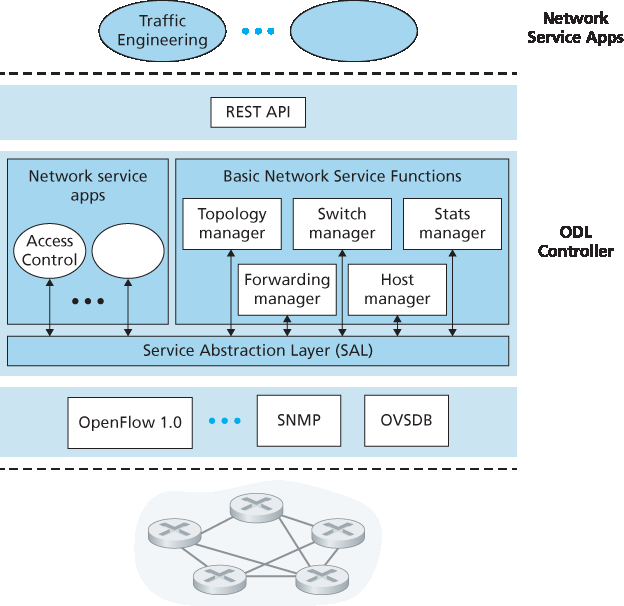
图 5.17 OpenDaylight 控制器
ODL 的 基本网络服务功能 是控制器核心,与 图 5.15 中的网络状态管理能力高度对应。SAL 是控制器的神经中枢,允许组件和应用调用彼此服务并订阅其生成的事件。同时,SAL 提供了对通信层特定 底层通信协议 的统一抽象接口,包括 OpenFlow 和 SNMP(简单网络管理协议,我们将在 第 5.7 节 中介绍)。OVSDB 是一种用于管理数据中心交换的协议,是 SDN 技术的重要应用领域。我们将在 第 6 章 介绍数据中心网络。
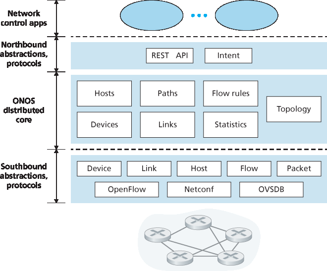
图 5.18 ONOS 控制器架构
- ONOS 控制器
图 5.18 展示了 ONOS 控制器的简化视图 [ONOS 2016]。类似于 图 5.15 中的典型控制器,ONOS 控制器可分为三层:
北向抽象与协议。ONOS 的独特之处在于其意图框架,允许应用请求高层服务(例如,建立主机 A 与主机 B 之间的连接,或阻止两者通信),而无需了解该服务的具体实现细节。网络状态信息通过北向 API 以同步查询或异步监听(例如网络状态变化时)形式提供给网络控制应用。
分布式核心。ONOS 的分布式核心维护网络链路、主机和设备的状态。ONOS 部署在一组互联服务器上,每台服务器运行相同的 ONOS 软件副本;服务器数量的增加带来服务容量的提升。ONOS 核心提供服务复制与实例间协调机制,为上层应用和下层网络设备提供逻辑集中核心服务的抽象。
南向抽象与协议。南向抽象屏蔽了底层主机、链路、交换机和协议的异构性,使分布式核心对设备和协议保持无关性。由于该抽象,分布式核心下方的南向接口在逻辑层级上高于我们在 :ref:`图 5.14 <Figure 5.14>`(典型控制器)或 :ref:`图 5.17 <Figure 5.17>`(ODL 控制器)中的设计。
Although the intense interest in SDN is a relatively recent phenomenon, the technical roots of SDN, and the separation of the data and control planes in particular, go back considerably further. In 2004, [Feamster 2004, Lakshman 2004, RFC 3746] all argued for the separation of the network’s data and control planes. [van der Merwe 1998] describes a control framework for ATM networks [Black 1995] with multiple controllers, each controlling a number of ATM switches. The Ethane project [Casado 2007] pioneered the notion of a network of simple flow-based Ethernet switches with match-plus-action flow tables, a centralized controller that managed flow admission and routing, and the forwarding of unmatched packets from the switch to the controller. A network of more than 300 Ethane switches was operational in 2007. Ethane quickly evolved into the OpenFlow project, and the rest (as the saying goes) is history!
Numerous research efforts are aimed at developing future SDN architectures and capabilities. As we have seen, the SDN revolution is leading to the disruptive replacement of dedicated monolithic switches and routers (with both data and control planes) by simple commodity switching hardware and a sophisticated software control plane. A generalization of SDN known as network functions virtualization (NFV) similarly aims at disruptive replacement of sophisticated middleboxes (such as middleboxes with dedicated hardware and proprietary software for media caching/service) with simple commodity servers, switching, and storage [Gember-Jacobson 2014]. A second area of important research seeks to extend SDN concepts from the intra-AS setting to the inter-AS setting [Gupta 2014].
PRINCIPLES IN PRACTICE
- SDN Controller Case Studies: The OpenDaylight and ONOS Controllers
In the earliest days of SDN, there was a single SDN protocol (OpenFlow [McKeown 2008; OpenFlow 2009]) and a single SDN controller (NOX Gude 2008). Since then, the number of SDN controllers in particular has grown significantly [Kreutz 2015]. Some SDN controllers are company-specific and proprietary, e.g., ONIX [Koponen 2010], Juniper Networks Contrail [Juniper Contrail 2016], and Google’s controller [Jain 2013] for its B4 wide-area network. But many more controllers are open-source and implemented in a variety of programming languages [Erickson 2013]. Most recently, the OpenDaylight controller [OpenDaylight Lithium 2016] and the ONOS controller [ONOS 2016] have found considerable industry support. They are both open-source and are being developed in partnership with the Linux Foundation.
- The OpenDaylight Controller
Figure 5.17 presents a simplified view of the OpenDaylight Lithium SDN controller platform [OpenDaylight Lithium 2016]. ODL’s main set of controller components correspond closely to those we developed in Figure 5.15.
Network-Service Applications are the applications that determine how data-plane forwarding and other services, such as firewalling and load balancing, are accomplished in the controlled switches. Unlike the canonical controller in Figure 5.15, the ODL controller has two interfaces through which applications may communicate with native controller services and each other: external applications communicate with controller modules using a REST request-response API running over HTTP. Internal applications communicate with each other via the Service Abstraction Layer (SAL). The choice as to whether a controller application is implemented externally or internally is up to the application designer; the particular configuration of applications shown in Figure 5.17 is only meant as an example.
Figure 5.17 The OpenDaylight controller
ODL’s Basic Network-Service Functions are at the heart of the controller, and they correspond closely to the network-wide state management capabilities that we encountered in Figure 5.15. The SAL is the controller’s nerve center, allowing controller components and applications to invoke each other’s services and to subscribe to events they generate. It also provides a uniform abstract interface to the specific underlying communications protocols in the communication layer, including OpenFlow and SNMP (the Simple Network Management Protocol—a network management protocol that we will cover in Section 5.7). OVSDB is a protocol used to manage data center switching, an important application area for SDN technology. We’ll introduce data center networking in Chapter 6.
Figure 5.18 ONOS controller architecture
- The ONOS Controller
Figure 5.18 presents a simplified view of the ONOS controller [ONOS 2016]. Similar to the canonical controller in Figure 5.15, three layers can be identified in the ONOS controller:
Northbound abstractions and protocols. A unique feature of ONOS is its intent framework, which allows an application to request a high-level service (e.g., to setup a connection between host A and Host B, or conversely to not allow Host A and host B to communicate) without having to know the details of how this service is performed. State information is provided to network-control applications across the northbound API either synchronously (via query) or asynchronously (via listener callbacks, e.g., when network state changes).
Distributed core. The state of the network’s links, hosts, and devices is maintained in ONOS’s distributed core. ONOS is deployed as a service on a set of interconnected servers, with each server running an identical copy of the ONOS software; an increased number of servers offers an increased service capacity. The ONOS core provides the mechanisms for service replication and coordination among instances, providing the applications above and the network devices below with the abstraction of logically centralized core services.
Southbound abstractions and protocols. The southbound abstractions mask the heterogeneity of the underlying hosts, links, switches, and protocols, allowing the distributed core to be both device and protocol agnostic. Because of this abstraction, the southbound interface below the distributed core is logically higher than in our canonical controller in Figure 5.14 or the ODL controller in Figure 5.17.